AM Design Process

Additive Manufacturing design

Additive Manufacturing - a designers dream come true?!?

Additive Manufacturing offers a high degree of design freedom that is not possible with traditional manufacturing techniques such as machining or casting. While AM bring a set of advantages such as tool-less production in low quantities that can be realized without redesigning the part, the full potential of the technology can only be realized when redesigning parts.

This freedom requires designers to rethink the way they learned to design for traditional manufacturing techniques. 

The AM Design Process

Rethink the product before re-designing it

The conventional design process needs to be at least partially adapted in order to get the most out of Additive Manufacturing. The key point is to re-think the product and its function before diving too deep into design guidelines and creating the actual file. 

We have summarized the main steps of the AM design process below. Each step is explained using the example of the following valve block that is redesigned with the goal to optimize the cooling and to replace it by an active cooling element.

Original design of the valve block

Original design / part idea

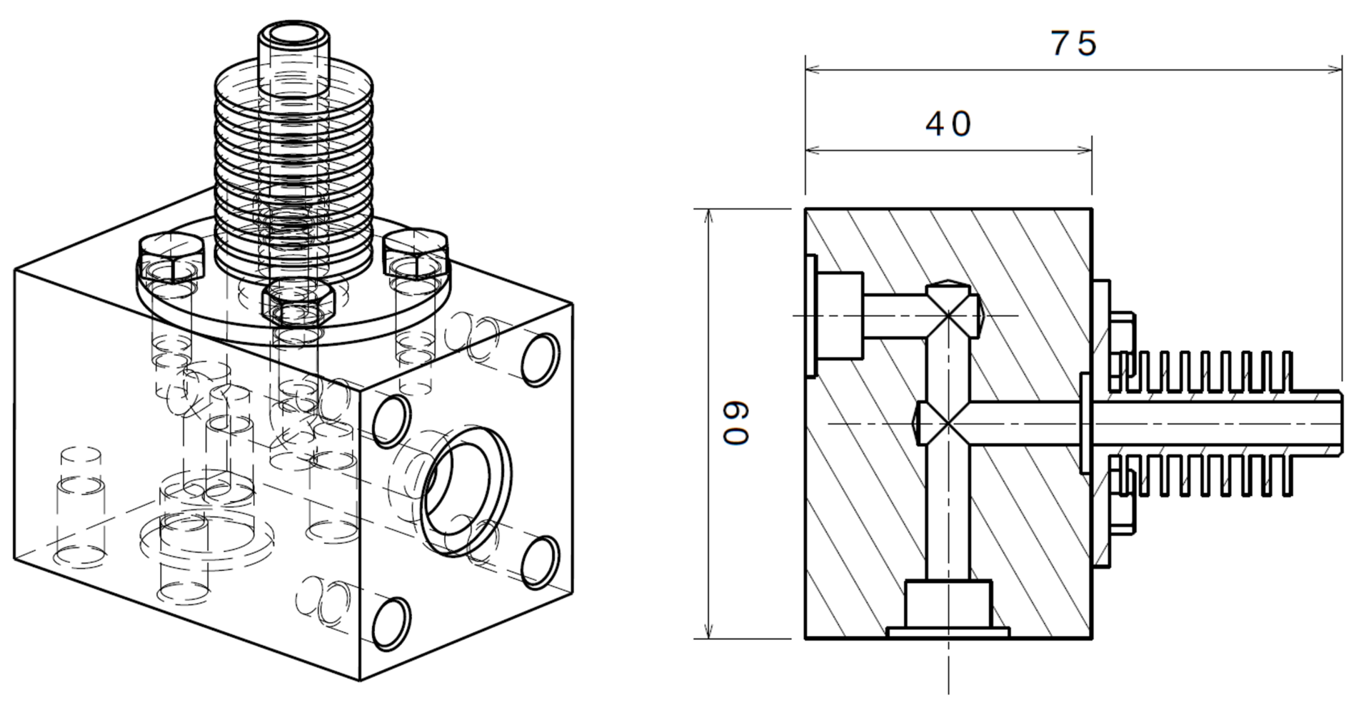
The AM design process can both be applied to existing designs or ideas and concepts for new parts

1

Analyze functionality and integration potential

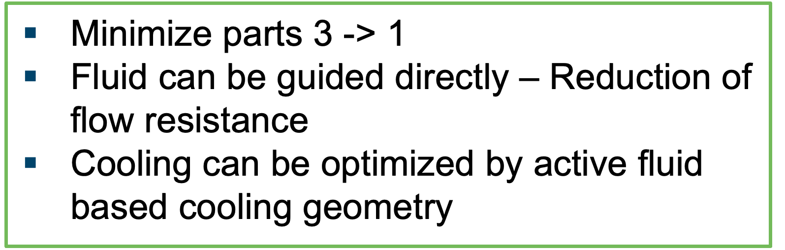
The starting point of the AM design process should always be the functionality of the part.

  • What are you trying to achieve with this application?
  • How would the part look like if there were absolutely no design restrictions
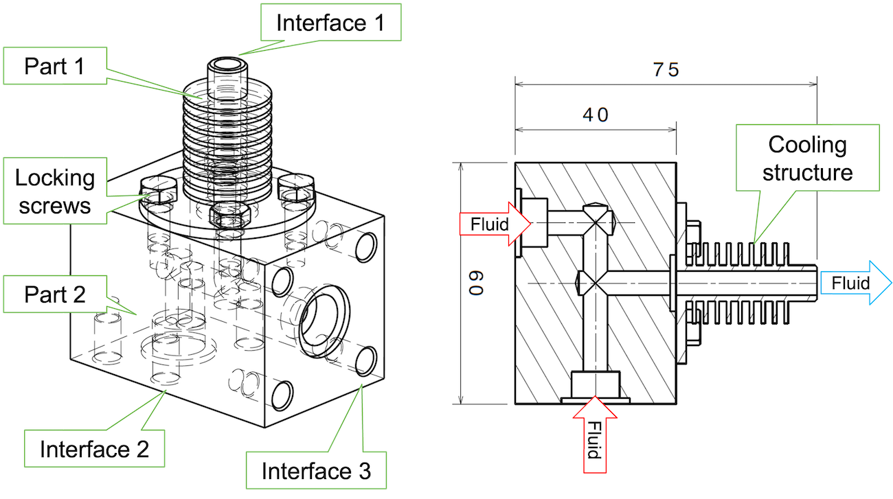
  • Which parts are connected to the application and can they be integrated into the design? 
2

Create new solutions and designs

Creating new solutions and ideas is probably the most important step.

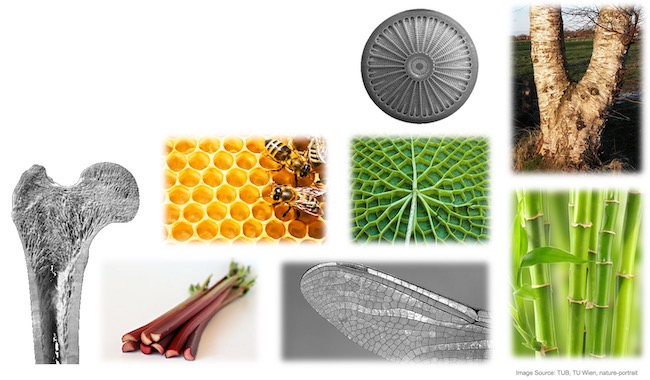
  • Use creative design methods.e.g. Design Thinking, biomimicry).
  • Do not judge crazy or bold design suggestions.
  • Build upon the concepts of others.  
3

Define non-design areas

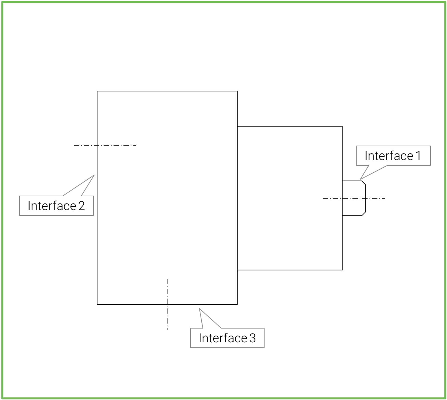
Define the boundary conditions and areas of the part that are fixed and cannot be changed

4

Define AM part orientation

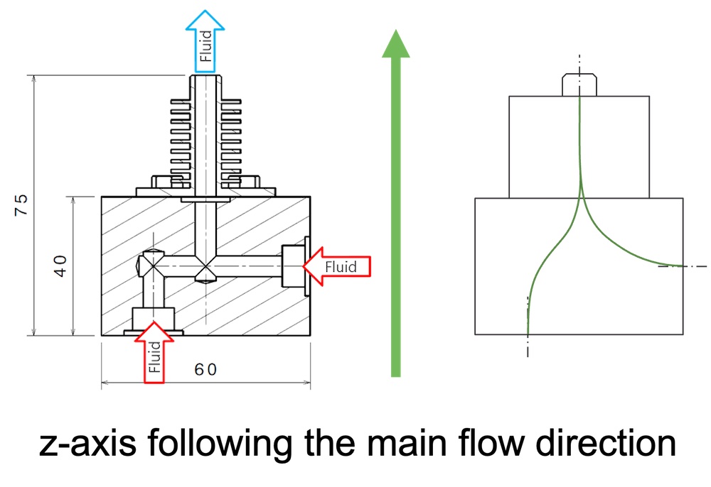
Defining the orientation is the first step when it comes to the actual design of the AM part. The orientation will influence all other design features. 
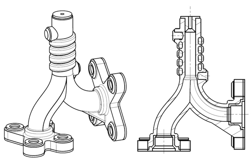
5

Design AM part geometry

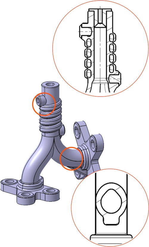
Once the orientation is fixed and non-design areas are defined, the actual AM part geometry needs to be designed. 

Technology-specific guidelines will help you during this phase. 
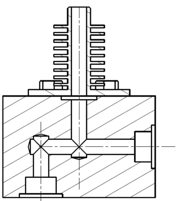
6

Add post processing offsets

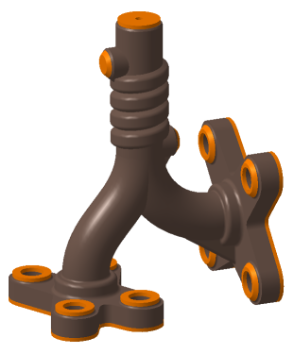
Define which areas will require post processing and add machining allowances to the surfaces. 

This usually requires having a discussion with the machining company. 

7

Finalize AM part

The last step is to document everything and to review the part internally. 

8

Old design

  • 7 parts
  • 1 Assembly step
  • 746 g mass

New design

  • 1 part
  • 0 assembly steps
  • 117 g mass
  • Reduced flow resistance
  • Active cooling integrated

Integral design concepts

Integrate surrounding parts and functions

Using integral design concepts is one of the fundamental approaches when designing for Additive Manufacturing. Understanding the entire system and then integrating as much into the design at hand often leads to impressive reductions in complexity, assembly time, manufacturing operations and ultimately cost. 

The A380 fuel connector study that can be seen on the left is a good example for integral design. In this case, 14 conventional parts have been integrated into 1, which led to a reduction in manufacturing operations from 18 to 5. The ultimate led to 50% lower cost of the new design compared to the conventionally produced parts. 


Image source: AIRBUS
Image source: GE


Another great example is the Advanced Turboprop (ATP) engine from GENERAL ELECTRIC (GE). GE completely rethought the entire design of the ATP engine with AM in mind and could achieve some impressive results:

  • Reduction of over 800 individual components into 11 AM parts
  • 35% of total assembly manufactured
  • Significantly improved fuel efficiency.

Another great way for Additive Manufacturing to add value is by integrating functionality into components. Typical examples for this include the introduction of heating or cooling channels or filters into parts. 

Topology Optimization

Part optimization according to load cases

Topology optimisation (TO) is a computer-based design process that uses mathematical algorithms to optimise the shape and material distribution of a structure or product, with the goal of improving its performance characteristics. While TO is not directly linked to AM, the design freedom of AM allows for the direct production of the complex shapes that are usually the outcome of the optimization. The principle of only using material wherever necessary additionally saves production cost for since with AM the costs are usually driven by the part volume. 

The TO process is described on a high level on the right side and demonstrated using a bracket in the video below.

Illustration of the topology optimization process. Source: Bensoe

Demonstration video of the topology optimization process. Video Source: CAESS ProTOp

Biomimetics

Design inspiration from nature

Biomimetics, also known as biomimicry, is the study of nature’s design and function to develop new materials, products, and technologies that solve human problems.

The benefits of drawing inspiration from nature are manifold, such as optimized material efficiency, homogenization of stresses, redudction of peak stresses and increased bending stiffness. Similiar to Topology Optimization, this concept is not directly linked to AM but the design freedom makes it a good fit. 

Sinter-based AM technologies and process chain

Sinter-based AM - a technology overview

Many different printing technologies - one sintering process

The sinter-based AM (SBAM) technologies have, as the name suggests, the sintering process in common. In this process, the printed green part is consolidated into a dense part and receives its final properties. The green part can be printed in advance using different technologies.They all have in common that metal powder is bound to the desired shape by a binder. The best-known printing technologies include Binder Jetting and Filament Material Extrusion.

In this section, you learn everything about the sinter-based AM  process chain and get an overview of the different printing technologies.

Goal and structure of this course

This course is aimed at engineers, designers and other professionals that are working closely with sinter-based AM technologies. The goal is to cover the most important aspects that will enable engineers and designers to fully grasp the capabilities and technical limitations of the printing technologies and the sintering process to succeed in technology selection and part design. Besides going through the course from the beginning until the end, this course can also act as a constant source of knowledge while working on AM projects. 

The course is structured into the following sections.

This section will start with an overview of the sinter-based AM process chain and its printing technologies, followed by a technology deep dive into the most important aspects of the BJT technology, followed by a closer look at the debinding and sintering step also including sintering simulation .

The second section will provide an overview of the different materials that are available as well as part characteristics that can be achieved with the BJT process and typical methods for quality assurance. Finally, several common defects in the BJT process are presented. 

The last section will act as a guideline for designers. Besides generally describing the process when designing for Additive Manufacturing, actionable restrictions and guidelines for the BJT process are provided. The final section will present several design examples from different industries. 

What you will find in this section

Sinter-based AM process chain

From digital model to finished part

Data preparation

Simulation to compensate the deformation during the sintering step, nesting of parts and definition of printing parameters

Printing

Through various printing processes, different feedstocks such as metal powders, filaments, pellets or dispersions are processed into green parts

Unpacking

Unpacking of fragile green parts needs to be done carefully and is typically a manual process.

Debinding

Debinding describes the process of removing the binder which results in a brown part

Sintering

To reach the structural integrity of a metal part, a sinter process is required. The powder particles fuse together to a coherent, solid structure via a mass transport that occurs at the atomic scale driven via diffusional forces.

The brown part shrinks ~13-21 % in each direction.

The process chain of sinter-based technologies differs from other AM Technologies. Especially the post-printing processes (debinding and sintering) are crucial to achieve the intended mechanical properties.

Technology principle

How does Binder Jetting work?

Binder Jetting is a powder based Additive Manufacturing technology in which a liquid polymer binder is selectively deposited onto the powder bed binding the metal particles and forming a green body.

The metal powder is applied to a build platform in a typical layer thickness of 40 µm to 100 µm. Subsequently a modified 2D print head apply a binder selectively onto the powder bed. Depending on machine technology a hardening or curing process of the binder is performed in parallel for each layer and/or at the end of the whole build. During the in-situ curing process a heat source is used to solidify the binder and form a solid polymer – metal powder composite.

Working Principle of Binder Jetting

Afterwards the build platform moves downward by the amount of one layer thickness and a new layer of powder is applied. Again, the liquid binder is deposited and hardened in the required regions of the next layer to form the green body. This process is repeated until the complete part is printed. After the complete printing process is finished the parts have to be removed from the “powder cake” meaning the surrounding loose but densified powder. To improve the removal of the excess powder from the green body often brushes or a blasting gun with air pressure are used.

To create a dense metal part the 3D printed green body has to be post-processed in a debinding and sintering process. Similar to the metal injection molding process BJT parts are placed in a high temperature furnace, where the binder is burnt out and the remaining metal particles are sintered together. The sintering results in densification of the 3D printed green body to a metal part with high densities of 97 % to 99,5%, dependent of the material.

Printing Technologies

Metal Binder Jetting

Binder Jetting is a powder based Additive Manufacturing technology in which a liquid polymer binder is selectively deposited onto the powder bed binding the metal particles and forming a green body.

The metal powder is applied to a build platform in a typical layer thickness of 40 µm to 100 µm. Subsequently a modified 2D print head apply a binder selectively onto the powder bed. Depending on machine technology a hardening or curing process of the binder is performed in parallel for each layer and/or at the end of the whole build. During the in-situ curing process a heat source is used to solidify the binder and form a solid polymer – metal powder composite.

Working Principle of Binder Jetting

Material Extrusion

Binder Jetting is a powder based Additive Manufacturing technology in which a liquid polymer binder is selectively deposited onto the powder bed binding the metal particles and forming a green body.

The metal powder is applied to a build platform in a typical layer thickness of 40 µm to 100 µm. Subsequently a modified 2D print head apply a binder selectively onto the powder bed. Depending on machine technology a hardening or curing process of the binder is performed in parallel for each layer and/or at the end of the whole build. During the in-situ curing process a heat source is used to solidify the binder and form a solid polymer – metal powder composite.

Working Principle of Binder Jetting

Mold Slurry Deposition

Binder Jetting is a powder based Additive Manufacturing technology in which a liquid polymer binder is selectively deposited onto the powder bed binding the metal particles and forming a green body.

The metal powder is applied to a build platform in a typical layer thickness of 40 µm to 100 µm. Subsequently a modified 2D print head apply a binder selectively onto the powder bed. Depending on machine technology a hardening or curing process of the binder is performed in parallel for each layer and/or at the end of the whole build. During the in-situ curing process a heat source is used to solidify the binder and form a solid polymer – metal powder composite.

Working Principle of Binder Jetting

Metal Selective Laser Sintering

Binder Jetting is a powder based Additive Manufacturing technology in which a liquid polymer binder is selectively deposited onto the powder bed binding the metal particles and forming a green body.

The metal powder is applied to a build platform in a typical layer thickness of 40 µm to 100 µm. Subsequently a modified 2D print head apply a binder selectively onto the powder bed. Depending on machine technology a hardening or curing process of the binder is performed in parallel for each layer and/or at the end of the whole build. During the in-situ curing process a heat source is used to solidify the binder and form a solid polymer – metal powder composite.

Working Principle of Binder Jetting