Design examples – metal L-PBF
Design examples
What do successful metal Additive Manufacturing applications have in common?
Early movers of successful Additive Manufacturing applications have in common, that they originate from high end and high value component manufacturing. Typical examples are the medical, aviation, turbine, space as well as oil & gas industry. A little later, the machine industry became aware of the potential for metal Additive Manufacturing, too. Especially the tooling industry and special machinery in high-end segments are promoting the development of metal Additive Manufacturing applications.
Below we have summarized selected LPBF applications from different industries and in different materials.
What you will find in this section
Hydraulic valve block for AIRBUS A380
Optimized AM design for a high-pressure hydraulic valve block
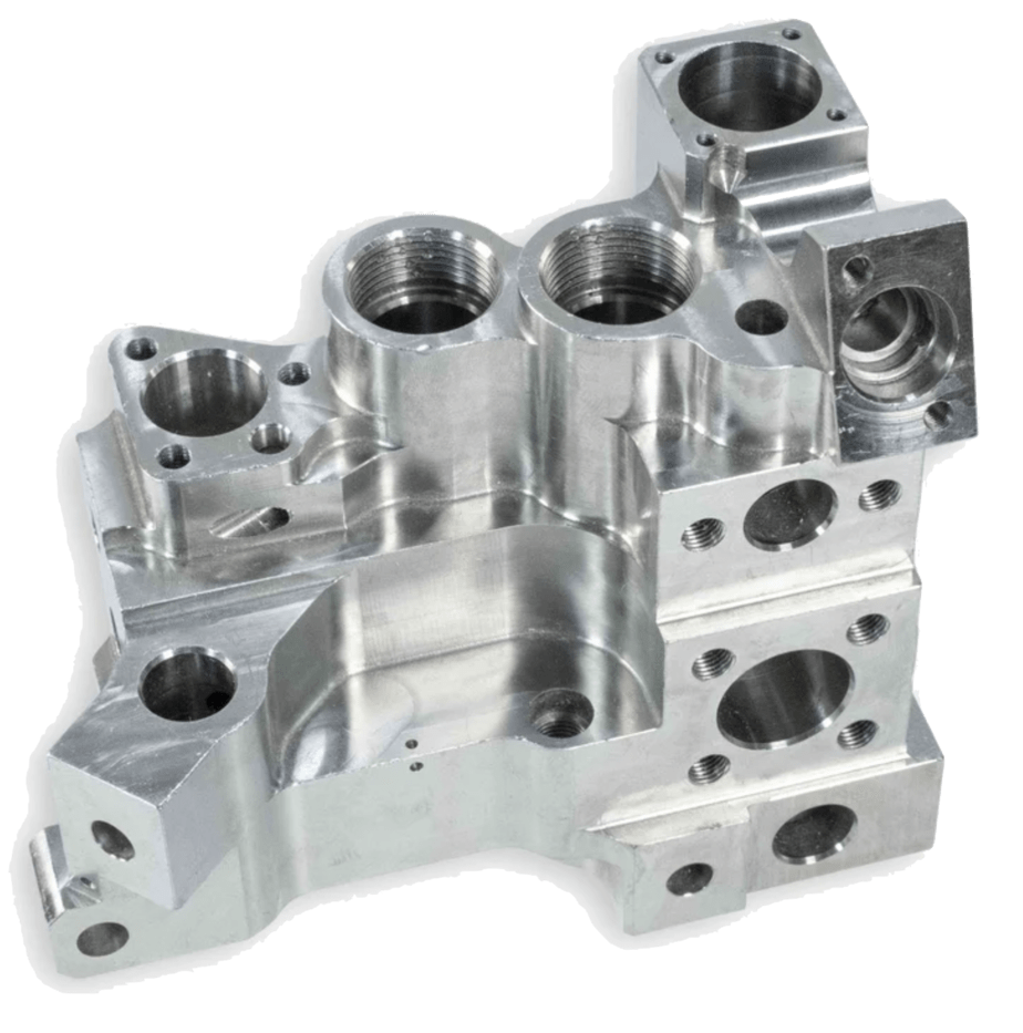
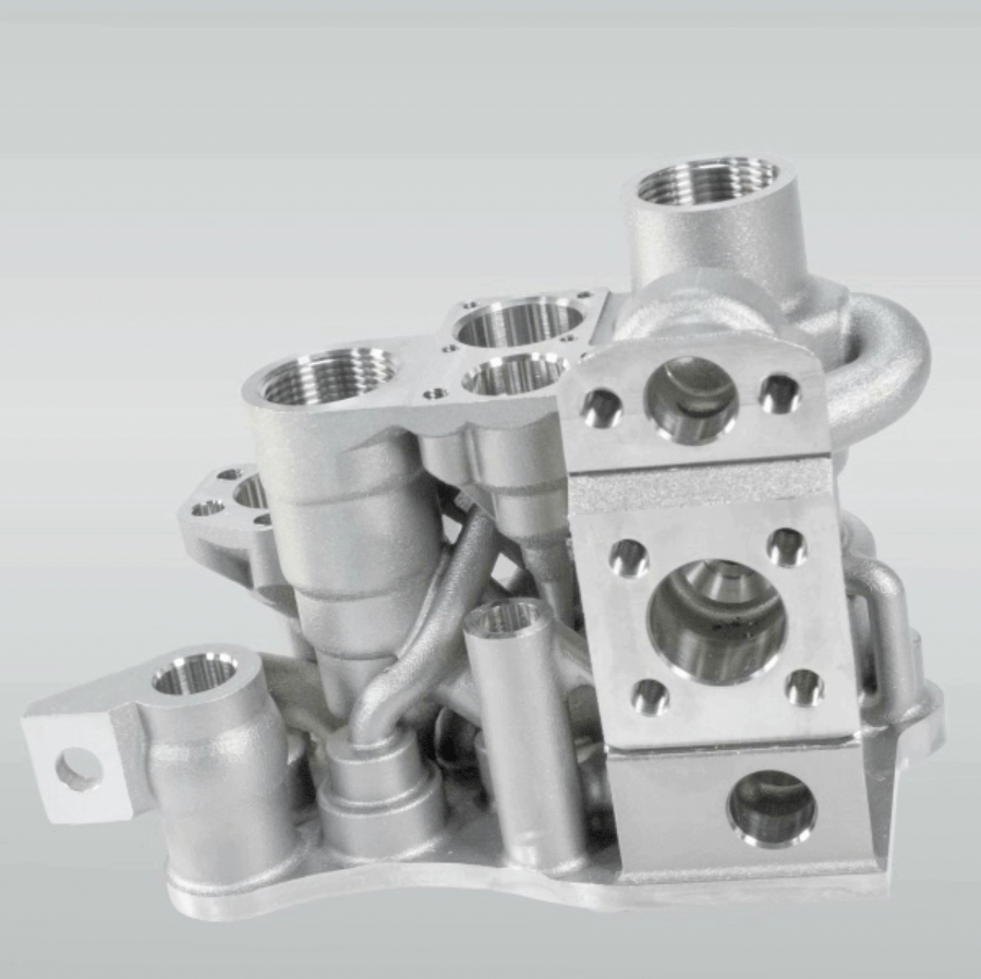
Source: EOS
User
Liebherr Aerospace / Airbus
Industry
Aerospace
Material
Stainless Steel
Classification
Qualified end part
Benefits of Additive Manufacturing
- Weight reduction of 35% compared to conventional valve block
- The new design integrated 10 functional elements into the new valve block, eliminating the complex piping system
- 75% less production time: The new design eliminates several manufacturing steps and can be printed in 1 day.
- Identical performance figures to milled component from titanium forging
Gas burner for glass surface treatment
Optimized internal channels for improved gas flow and avoidance of support structures
User
Linde
Industry
Industrial
Material
Maraging Steel MS1
Classification
Qualified end part
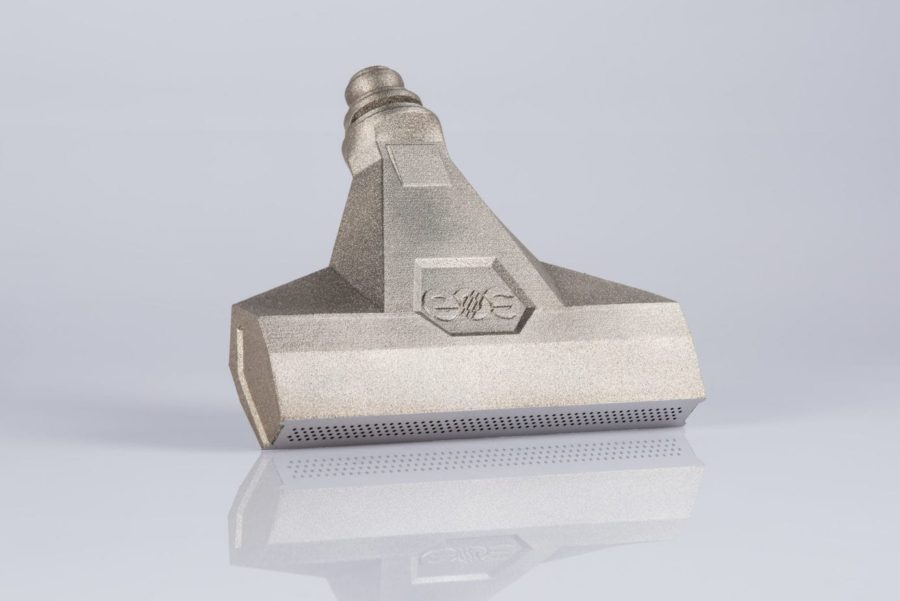
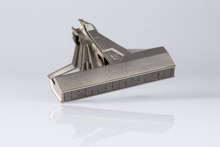
Source: EOS
Benefits of Additive Manufacturing
- Functional Integration: Integration of 15 individual components into 1, avoiding weld seams
- Efficient: Homogenous flame front leads to good results during the surface glass treatment process
- Short leadtime: 18 parts can be produced in one medium-sized printer, the printing time per part is 5 hours
- Increased lifespan: Improved cooling channel design to reduce the thermal stress
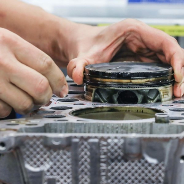
911 GT2 RS Piston
Lightweight piston with integrated cooling duct
User
Dr. Ing. h.c.F. PORSCHE AG
Industry
Automotive
Material
Aluminium
Classification
Qualified end part
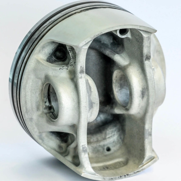
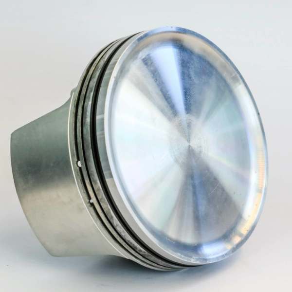
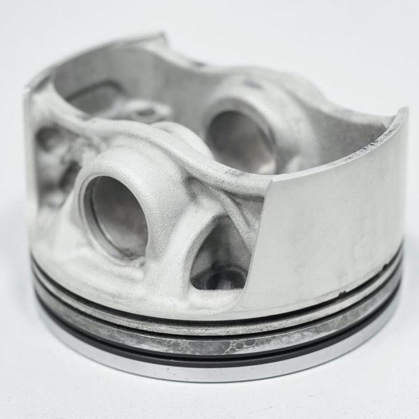
Benefits of Additive Manufacturing
- Weight reduction of 10% compared to the forged series production pistons
- Increased engine speed and up to 30 HP more power
- Lower temperature load
- Optimized combustion and improved efficiency
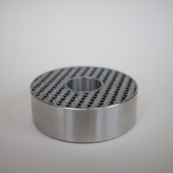
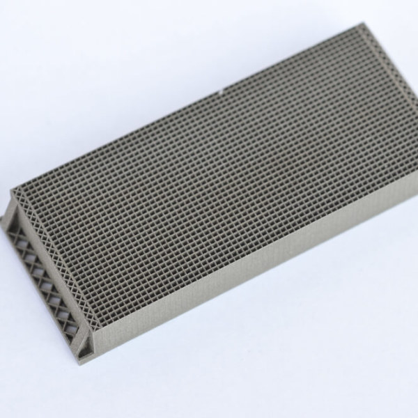
Catalytic reactors
Air purification component with optimized structure
User
ADDCAT
Industry
Industrial
Material
Stainless Steel
Classification
End part
Benefits of Additive Manufacturing
- Increased thermal conductivity thanks to design freedom
- Energy efficient process by recovering the energy released from the reactor
- Efficient conversion in a small reactor volume thanks to large surface area and low pressure drop
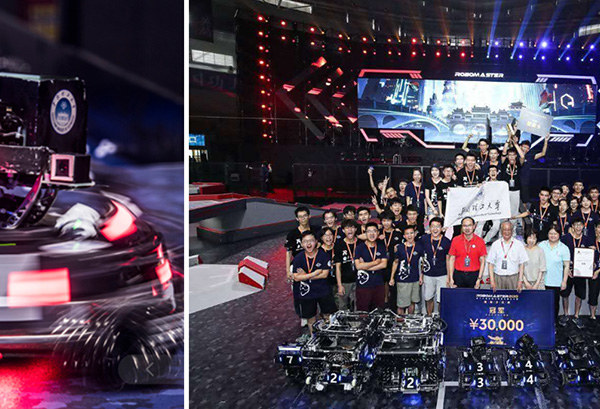
Stabilizer mount for a robot
Additive Manufacturing in Robotics Competition
User
South China University of Technology
Industry
Mechanical Engineering
Material
Aluminium
Classification
Functional Prototype
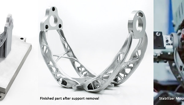
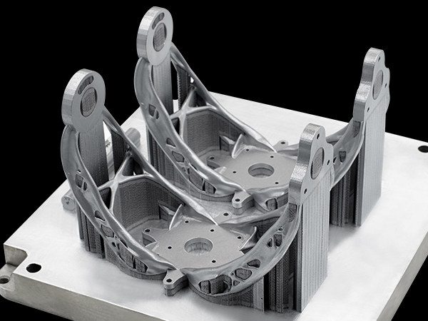
Benefits of Additive Manufacturing
- Integration of 27 parts into 1 component
- Weight reduction of 170 grams – a 42% weight reduction compared to the original CNC process
- Production of 2 sets of stabilizers in 2 days
Anti-scatter grid
Thin wall structures to enhance image quality
User
DUNLEE
Industry
Medical
Material
Tungsten
Classification
Qualified end part
Benefits of Additive Manufacturing
- Production of 100 micron thick walls at a positional accuracy of 25 microns
- Energy efficient process by recovering the energy released from the reactor
- Efficient conversion in a small reactor volume thanks to large surface area and low pressure drop
ARNO Cutting Tool
Patented coolant design for cutting tool
User
ROSSWAG
Industry
Tooling & Moulding
Material
Tool Steel
Classification
Tools and fixtures
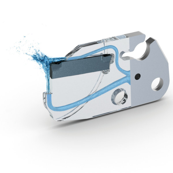
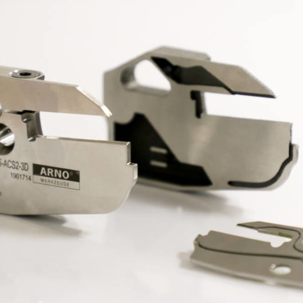
Benefits of Additive Manufacturing
- Patented coolant supply design
- Coolant is directly delivered to the cutting zone for higher efficiency
- Increased tool life and higher process security
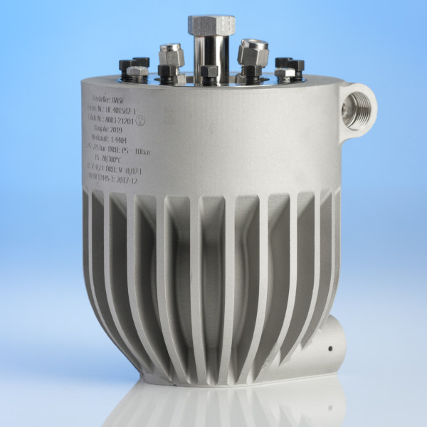
Autoclave for High Pressure Applications
Autoclave at 225 bar operating pressure
User
BASF
Industry
Mechanical Engineering
Material
Stainless Steel
Classification
Qualified end part
Benefits of Additive Manufacturing
- Certified according to European Pressure Equipment Directive (2014/68/EU) Category III
- Working at an operating pressure of 225 bar
- The design features a more than two meter long interior channel for tempering fluid which winds around the container wall
- The AM design enables faster temperature cycles, better regulation of an even temperature distribution as well as optimized tempering of the component
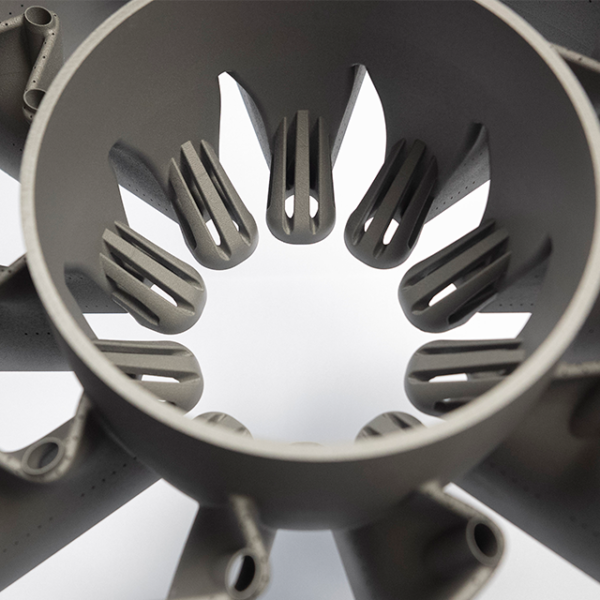
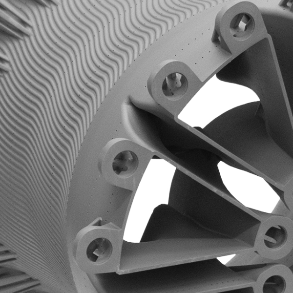
Combustion chamber
Patented coolant design for cutting tool
User
GF CASTING SOLUTIONS
Industry
Energy & Powerplant
Material
Nickel based alloy
Classification
Qualified end part
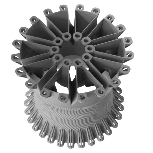
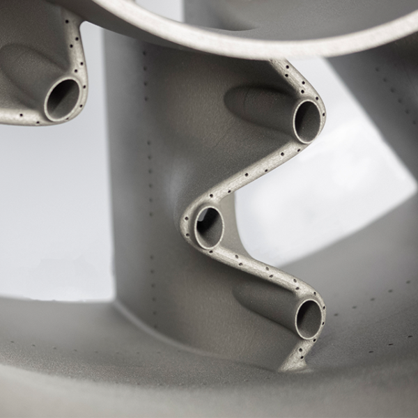
Benefits of Additive Manufacturing
- Integrative housing design including static vanes
- Significant cost and delivery time reduction due to functional integration
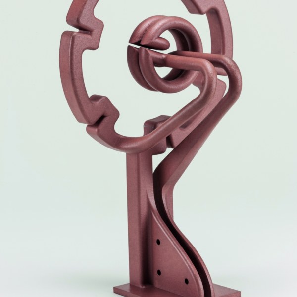
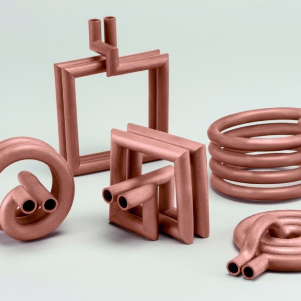
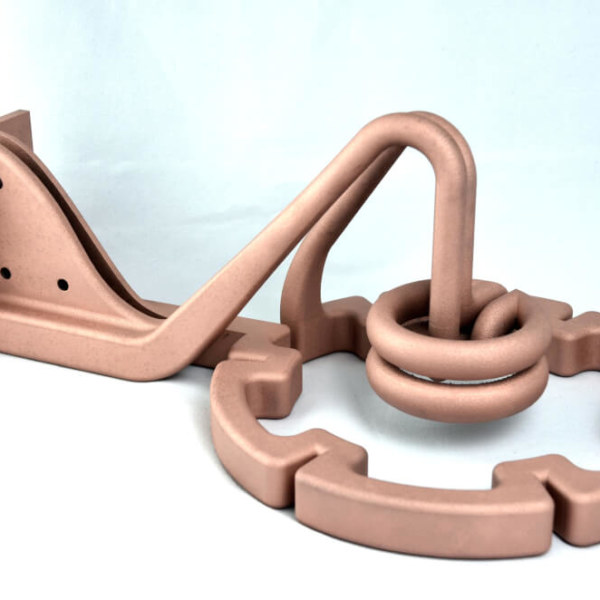
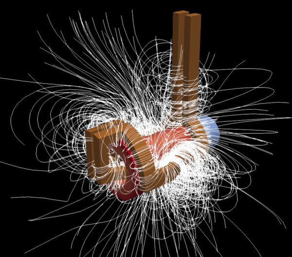
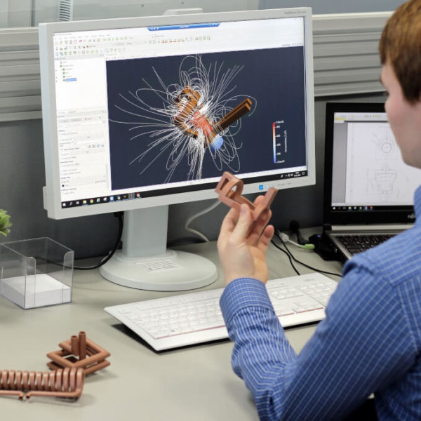
Optimized induction coils
Inductuon coils printed in copper
User
PROTIQ
Industry
Mechanical Engineering
Material
Copper
Classification
Non-qualified end part
Benefits of Additive Manufacturing
- Freedom of design of the LPBF process offers new possibilities for coil design
- The shape of the coil can be optimally adapted to the component to be heated.
- AM production of an induction coil takes only a few days, conventional production takes up to several weeks.
- The reproducibility of the coil is higher than manufactured conventially
Ion Engine Mount
AM optimized space components
User
THE BOEING CO.
Industry
Space
Material
Aluminium
Classification
Qualified end part
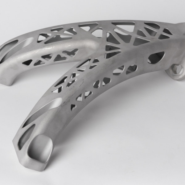
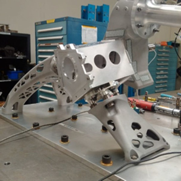
Benefits of Additive Manufacturing
- The 702MP deployable ion engine mount includes three pieces that are 3D printed and work as an integrated assembly
- The mission-critical part is standard on every 702MP derived spacecraft with xenon ion propulsion.


