L-PBF technology principle and machine technology
Laser Powder Bed Fusion - technology deep dive
The leading metal AM technology today
L-PBF or Laser Beam Powder Bed Fusion, also known as Selective Laser Melting (SLM), is the most known metal Additive Manufacturing technology. With an installed base of several thousand systems, the technology is now widespread and used in many applications in production. This section gives a broad overview of the state of the art of Laser Powder Bed Fusion.
Goal and structure of this course
This course is aimed at designers and other professionals that are working closely with metal Laser Powder Bed Fusion technology. The goal is to cover the most important aspects that will allow designers to fully grasp the possibilities and technical limitations to design parts for the technology. This course does not teach the operation of a printer or AM software. Besides going through the course from the beginning until the end, this course can also act as a constant source of knowledge while working on AM projects.
The course is structured into the following sections.
This section will start with a technology deep dive into the most important aspects of the L-PBF technology, followed by a closer look at the L-PBF process chain as well as the L-PBF process itself.
The second section will provide an overview of the different materials that are available as well as part characteristics that can be achieved with the L-PBF process and typical methods for quality assurance. Finally, several common defects in the L-PBF process are presented.
The last section will act as a guideline for designers. Besides generally describing the process when designing for Additive Manufacturing, actionable restrictions and guidelines for the L-PBF process are provided. The final section will present several design examples from different industries.
What you will find in this section
Technology principle
How does Laser Powder Bed Fusion work?
Laser Powder Bed Fusion (L-PBF) is based on melting of a powder feedstock by exposure with laser radiation. The powder material is applied by a leveling system in a predefined layer thickness to a substrate plate fixed on the build platform. The leveling system can be a blade, brush or roller that applies a predefined amount of powder from a reservoir and spreads it on the substrate plate. Alternatively, the powder container itself is moved across the substrate plate and distributes the powder evenly.
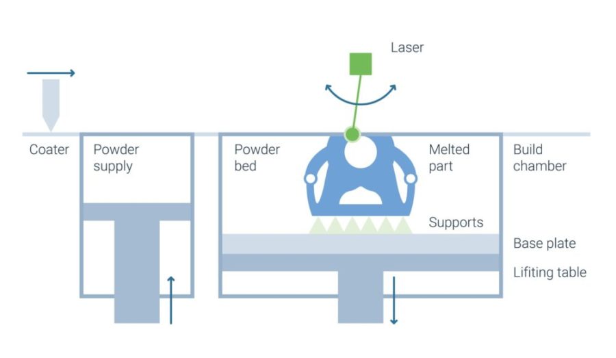
The energy for bonding the powder particles is provided by a laser. The laser beam is directed on the powder bed so that it selectively melts the powder. Machine development started with one laser source and optic, today many production systems use multiple lasers to increase productivity. For guiding the laser beam, often a mirror deflection system is used. Furthermore, machine systems exist in which the laser is moved via a gantry with multiple axes. These solutions promise to be especially cost-efficient.
When the exposure process is completed, the build platform is lowered by the amount of the layer thickness and the next powder layer is applied. When re-exposing the next layer, it fuses with the previously generated layer. The process described is repeated until the entire component geometry is generated. The unexposed powder remains loose and can be recycled.
Because of the strong reaction tendency of metallic powders, the process takes place in protective atmosphere. Before starting the process, the build chamber is purged typically with argon or nitrogen, until an oxygen content of less than 0.1 % is reached. Alternatively, machines exist in which the process takes place under vacuum.
The most important process parameters are the laser power, scanning velocity, the layer thickness, the diameter of the laser beam focus and the scan strategy, that defines the pattern in which the powder is exposed. Optimal parameters differ depending on the metal alloy and the powder characteristics.
Video of the multi laser exposure process in LPBF of metals on SLM Solutions SLM500 QUAD. Video source: SLM Solutions
Laser Powder Bed Fusion with process gas
To avoid negative effects during the actual fusion process, such as oxygen pickup, usually the build chamber is flooded with a process gas to create an inert atmosphere. The protective atmosphere is typically achieved using argon or nitrogen to reach an oxygen content of less than 0.1%
Laser Powder Bed Fusion with vacuum
Instead of using a process gas to create an inert atmosphere, several machine suppliers offer systems that pull a vacuum inside of the build chamber to create the inert processing atmosphere.
Benefits of using a vacuum as inert atmosphere is use of less costly process gas. Process inherent material porosity in terms of voids can be closed during hot isostatic pressing, since there is no entrapped gas. Furthermore, processing under vacuum may have benefits on the undesired oxygen or nitrogen pickup. Downside of vacuum machines is the complex and usually costly system technology. Also, smoke residue during processing has to be dealt with. Among other suppliers, EVOBEAM is offering a L-PBF system where the build process runs under vacuum.
Machine suppliers 3D SYSTEMS and RENISHAW use the evacuation of the build chamber to minimize oxygen contamination before flooding the chamber with Argon gas. The actual melting process in these machines is not run under vacuum, but a highly purified inert gas atmosphere.
Hybrid Laser Powder Bed Fusion
Hybrid L-PBF systems are a combination of CNC milling and LPBF process. Offered by companies OPM LAB and MATSUURA, these machines enable in-situ milling of every other layer contour. After PBF processing of a layer, a milling head inside of the build chamber machines along the contours of the just created part layer to improve its surface quality. Through this strategy, all of the printed part surface can be processed via milling. However, this hybrid processing comes with a loss of productivity of the PBF process. The feasibility is highly part dependent. Today, the systems are almost exclusively used in mold and tool making industry, where a high surface quality is required.
Area-wise Powder Bed Fusion
Area-wise Laser Powder Bed Fusion is a proprietary process from SEURAT TECHNOLOGIES that uses a high power, pulsed laser source as well as complex optics to melt complete areas in one shot. The process mirrors the principle of Area-wise Vat Polymerization and therefore promises extremely high productivity. Since its introduction, the technology only marginally increased in its Industrialization Index, with first customers able to order parts. Further developments to reach maximal pulse rate and laser power are still ongoing and become increasingly difficult, if the projected melting rates want to be achieved. Due to the complexity and extremely high investment cost of the high-power laser source and especially the needed optical components it is most likely, that the technology will be used for part production only without external machine sales for the foreseeable future.
Machine technology
Main machine components of Laser Powder Bed Fusion systems
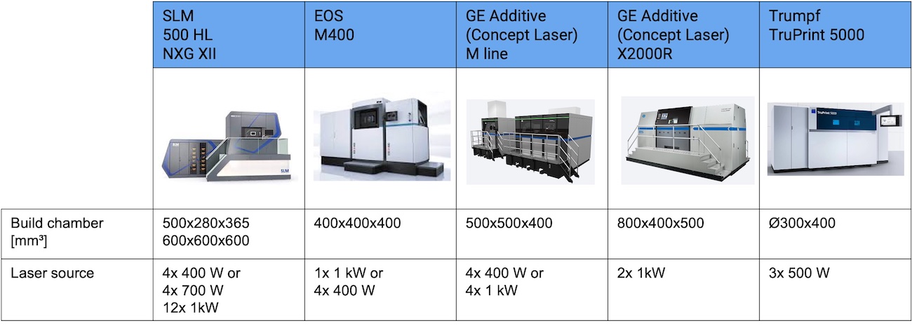
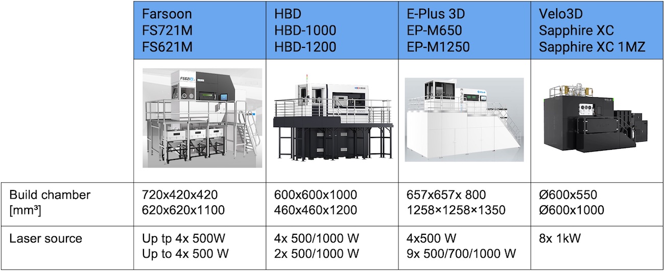
Basic components of L-PBF system technology are laser beam source, optical elements for beam shaping and guiding as well as a building chamber with a lifting table and powder feed system. Fist machine vendors such as TRUMPF equipped machines with green lasers due to improved absorption rate of wavelength for processing special alloys such as copper.
Almost exclusively, industrial L-PBF systems today use single-mode fiber lasers of wavelength 1 070 to 1 080 nm. Laser power ranges from 100 to 400 W for smaller LPBF systems up to 700 to 1 000 W. Galvanometer scanners deflect the laser beam using rotating mirrors in x- and y-direction. Beam forming is realized through collimation and focusing lenses. a recent trend in machine technology is to move away from f-theta lenses and pre-objective scanning systems towards post-objective setups with dynamic focusing systems to avoid process issues from focus shifts caused by thermal expansion of lenses. Dynamic focusing is also used for increased laser spots, especially in high power (1 000 W) machines.
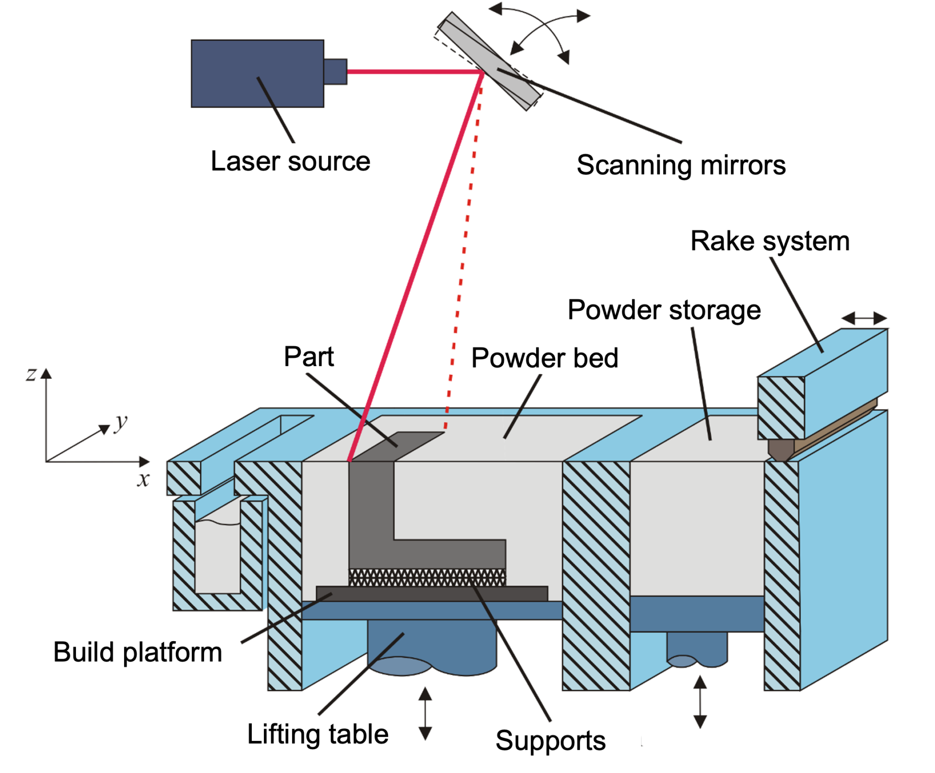
Multi-laser systems with 2 or more laser beam sources are available for increase of productivity. In such setups, either each laser processes a dedicated area of the build platform or alternative setups allow processing of the full area of the build platform with every laser beam. The second setup simplifies calibration of the of the beam positioning between all lasers and therefore improves quality control issues in the overlap region.
The build chamber is designed gas tight and is flooded with an inert gas such as argon or nitrogen prior to process start. Process smoke and particles are transported away from the fusion process by a directed gas stream within the build chamber and channeled through filtration systems. Variants exist which use a vacuum chamber instead of inert gas atmosphere for protection of the melting process. In general, machines as well as periphery for processing of reactive materials, such as titanium or aluminum alloys, require explosion protection measures.
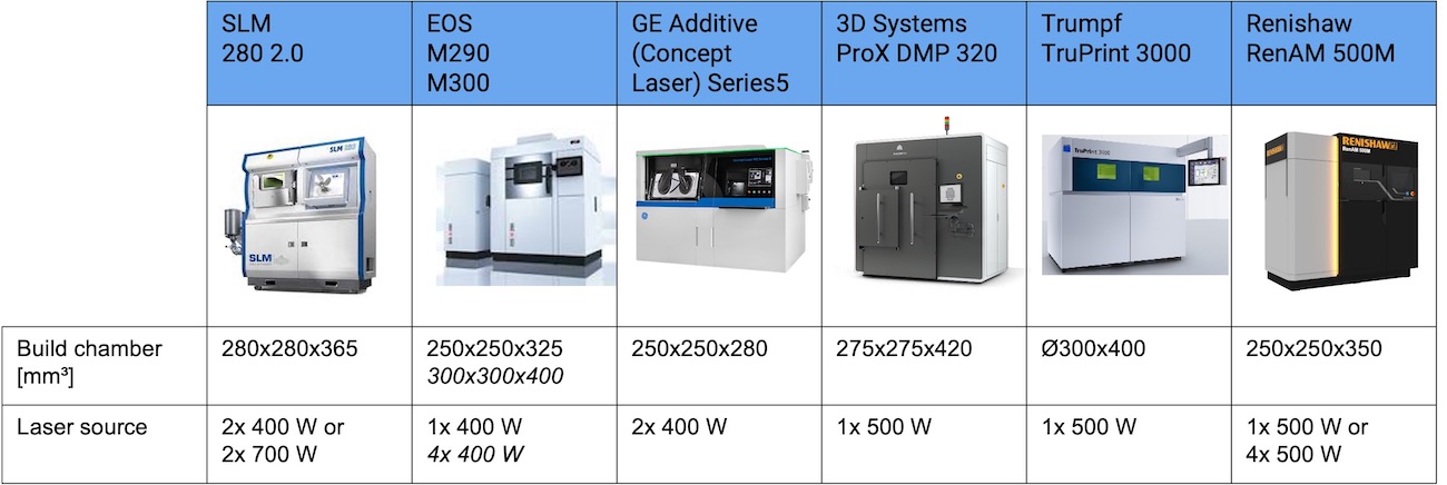
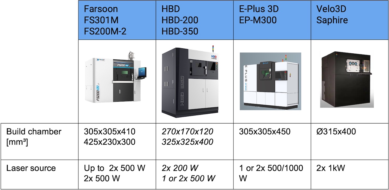
Machine size
Development history
How Laser Beam Powder Bed Fusion became the leading metal technology
A preliminary stage of L-PBF technology was the so-called Selective Laser Sintering (SLS), that was developed in 1988. Three dimensional objects were built layer-wise from CAD data with polymer powders. Later, the process was extended to the manufacture of metal parts by using polymer coated metal powders. In 1994, a process branded Direct Metal Laser Sintering (DMLS) was established by EOS. It allowed a direct one-step manufacturing of metal parts by using two-phase powder in a liquid-phase sintering process. In this process a low temperature melting component was mixed with higher temperature resistance powders. When exposed by the laser beam only the low melting component melted and formed a matrix around the remaining powder particles.
Since two-phase powder materials still did not match the properties of engineering materials, extensive research was done mainly at German universities to qualify single-phase powders for the DMLS process. Simultaneously, the machine technology was further developed at German system suppliers (CONCEPT LASER, EOS, SLM SOLUTIONS). Another machine system derived from the early principle was brought onto the market in 2003 by TRUMPF under the brand name of Direct Laser Forming (DLF). However, TRUMPF withdrew from the market after a short time due to the immaturity of the market and therefore limited sales potential.
Until 2010 the main development focus in universities and at the machine suppliers was on stabilizing the melting process. Due to many patents expiring in 2010 new players entered the market and could secure shares. With the Additive Manufacturing hype starting in 2013, the technology got a lot of attention and machine sales increased significantly. Within the last few years many new suppliers for L-PBF machines emerged utilizing lower cost components, unique scanning strategies and copying established systems. Additionally, large cooperations entered the market by buying smaller machine manufacturers. Today over 60 L-PBF machine supplier are active in the market.
Supply chain
L-PBF supply chain diversifies from machine OEMs
Historically, powder material was provided by the machine suppliers. Today, users are able to acquire suitable metal powders directly from material suppliers. Large powder suppliers from PM technologies as well as small AM specialized start-ups entered the AM powder market and today AMPOWER counts over 80 suppliers offering AM specific powder material in a large variety of alloys. A similar trend can be seen for machine technology. More peripheral devices, especially for powder handling, are introduced into the market by independent suppliers.
Software solutions for orientation and positioning of parts on the built platform and simulation of internal stresses are available from machine suppliers and directly from independent developers. The established CAD-CAM software houses are working on integrated software solutions with AM specific modules.
Technology development
A technology on the brink of full maturity
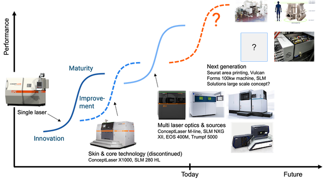
Laser Powder Bed Fusion still holds the top spot in technological maturity as well as in industry wide adoption. The use of L-PBF for the production of end parts in highly demanding industries such as medical, aviation and the energy sector has driven a continuous improvement of machine hardware and process reliability over the past five years.
Current developments concentrate on increasing productivity and part size on the one hand and low-cost solutions on the other. In 2021 SLM SOLUTIONS and VELO3D installed their first multi- laser machines with 12 and 8 lasers respectively at customer sites. Making them the most productive machines on the market. Additionally, with 600 mm in size the build plate allows for larger AM parts, allowing further applications in the turbine, energy and space industry. In 2021 ADDIRA showed its newest machine model with a build chamber of 1 m² allowing for even bigger parts. On the other side of the spectrum companies such as ONECLICK METAL and XACT METAL further established their low-cost L-PBF systems in the market. Priced at around EUR 100,000 they target small job-shops and companies to use PBF in dental, tooling and spare part applications.
Another trend is the continuous development in PBF specific software solutions. VELO3D and SLM SOLUTIONS offer data preparation and process control to minimize or eliminate support structures during the building process. GE ADDITIVE released a new software suite to incorporate the complete process chain and offer the customer new and improved functionalities and 3D SYSTEMS strengthened their software capabilities by the acquisition of multiple AM software start-ups from distortion simulation to MES solutions.
Advantages and disadvantages
Cost as the remaining threshold for a wider adoption
The main benefits of L-PBF technology are the good mechanical properties of the resulting parts, their high density and the fine resolution. The technology is well-established with a large variety of available metal alloys. It is a single-stage production that enables a high freedom of design. Scrap material is reduced through near net shape production and recycling of the unmelted powder.
However, internal residual stresses that are induced during cooling constitute a restriction since they can lead to part deformations or cracks. Support structures to counteract such stresses have to be removed after the building process. The relatively rough surface, moreover, typically requires several post-processing steps. The investment costs for machine systems as well as the feedstock material are considerably high and may pose a limiting factor on potential business cases.


