Mechanical properties of selected materials

Mechanical properties of selected materials

Tensile, elongation and fatigue properties

In this section you will find  overview tables of static mechanical properties including Ultimate Tensile Strength (UTS), Yield Strength (YS) and Elongation (epsilon) for the most common materials that are used for LPBF today. All values are based on material data sheets from selected machine OEMs and material suppliers. Average values are provided based on tensile samples that were printed in horizontal and vertical orientation. The values are provided in differnt material conditions. Without heat treatment in as build state as well as after typical heat treatments for the selected material. A more detailed breakdown including the spread from different suppliers can be downloaded as pdf on the course page

At the end of this section, general information about fatigue properties LPBF material is provided using the example of Ti-6Al-4V.

AlSi10Mg

State

UTS [MPa]

YS [MPa]

𝜀 [%]

Reference

240

140

1.0

No heat treatment

426

247

6.2

Stress relieved

300

178

12.9

T6

305

235

9.3

Reference: Die casted, DIN EN 1706, min. values

Stress relieved = Heat treated at 270°C and air cooled

T6 = Solution annealing at 530 °C, water quench and aging at 165 °C

Ti-6Al-4V (Grade5)

State

UTS [MPa]

YS [MPa]

𝜀 [%]

Reference

1110

1020

15

No heat treatment

1090

970

11.3

Stress relieved

1065

950

17.0

HIP

992

894

15.5

Reference = Wrought, AMS 4920, annealed

Stress relieved = Heat treated at 800 °C in vacuum or Argon

HIP = Hot Isostatic Pressing at 920 °C and 1000 bar

Ti-6Al-4V (Grade 23)

State

UTS [MPa]

YS [MPa]

𝜀 [%]

Reference

1170

1100

10

No heat treatment

1282

1094

8.3

Stress relieved

1094

1012

16.6

HIP

1018

920

17.7

Reference = Wrought, ASTM F136-13, min. values

Stress relieved = Heat treated at 800 °C in vacuum or Argon

HIP = Hot Isostatic Pressing at 920 °C and 1000 bar

IN718 (Nickel-base alloy 2.4668)

State

UTS [MPa]

YS [MPa]

𝜀 [%]

Reference

1030

1280

12

No heat treatment

1021

706

31.6

Solution annealed & aged

1451

1207

14.6

Solution annealed & double aged

1413

1236

16.5

Reference = Wrought, solution annealed, ASTM B637-18

Solution annelaed & aged = Solution annealed at 954 °C, quenched, aged at 718 °C

Solution annealed & double aged = Modified homogenization, solution annealed, double aged (according to ASTM F3055)

IN625 (Nickel-base alloy 2.4856)

State

UTS [MPa]

YS [MPa]

𝜀 [%]

Reference

940

430

51.5%

No heat treatment

966

674

36.4

Stress relieved

988

654

39.2

Solution annealed

959

591

40.0

Reference = Annealed at 1065 °C, ASTM B446

Stress Relieved = Stress relief at 870 °C, air cooled

Solution Annealed = Annealed at 1048 °C, furnace cooled

Hastelloy X

State

UTS [MPa]

YS [MPa]

𝜀 [%]

Reference

763

379

44

No heat treatment

791

588

34.4

Annealed & quenched

705

404

47.4

Solution annealed

744

383

48

Reference = Sheet material, ASTM B435

Annealed & quenched = Annealing at 1177 °C, water quenching

Solution annealed = Annealing at 1177 °C, air cooled

1.2709 (M300)

State

UTS [MPa]

YS [MPa]

𝜀 [%]

Reference

1000

900

13

No heat treatment

1163

998

11.8

Solution annealed

2243

2167

3.0

Aging

1951

1871

5.7

Reference = Plate material, solution treated, AMS 6521, min. values

Solution annealed = Solution treated at 940°C, air cooled, aged at 490°C

Aging = Aged at 500 °C

Stainless Steel 17.4PH

State

UTS [MPa]

YS [MPa]

𝜀 [%]

Reference

1170

1070

8

No heat treatment

1014

755

19.7

H900

1448

1303

11.2

Reference = Hot rolled plates, H925, ASTM A693, min. values

H900 = Solution treated, quenched, aged at 900 °F

Stainless Stel 316L

State

UTS [MPa]

YS [MPa]

𝜀 [%]

Reference

485

170

40

No heat treatment

618

510

43.4

Stress relieved

688

544

40.4

Quenched

569

339

52.5

Reference = Plate material, annealed, ASTM A240

Stress relieved = Stress relief at 550°

Quenched = Solution treatment at 1095 °C, water quenching

Fatigue properties

Fatigue performance of LPBF parts are strongly influenced by process inhertent material and part properties. Early fatigue failure occurs in LBPF parts due to the presence pores and a high surface roughness in as build conditions when compared to forged and machined material. To address these issues, post-processing techniques, such as surface polishing and hot isostatic pressing (HIP) can be applied. 

In this section we will compare fatigue properties of printed Ti-6Al-4V to forged material in different conditions. In general, similiar influences of the part properties on fatigue results can be observed for all LPBF materials. 

As build surface condition

Source: Eric Wycisk

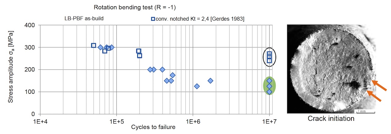
The chart compares fatigue performance of printed Ti-6Al-4V in as build surface condition to conventional samples with engineering notches. The resulting fatigue limit in as build specimen at 138 MPa is significantly lower than the notched conventional samples. The high surface roughness of the LPBF specimen results in multiple surface crack initiation and consequently early failure. Similar results can be obtained for Electron Beam Powder Bed Fusion (E-PBF), which has similar to worse surface properties in as build state.

HIPped and polished condition

Source: Eric Wycisk

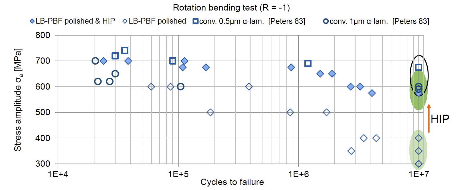
The chart above shows the influence of polishing and HIPing on the fatigue performance of printed Ti-6Al-4V. The 3 data points at the bottom right show that through polishing fatigue performance can be increased to ~300 – 400 MPa at 10^7 cycles. After additional HIP, a fatigue limit close to 600 MPa, which is comparable to wrought material can be achieved. 

Crack initiation due to stress concentration at process inherent micro porosity results in high scatter and reduced fatigue properties. Pores at or close to the surface lead to early failure while specimen with internal pores exhibit much longer lifetime to failure. Closing the pores by hot isostatic pressing reduces the scatter and increases the overall fatigue performance to levels of wrought and forged material.

Sinter-based AM technologies and process chain

Sinter-based AM - a technology overview

Many different printing technologies - one sintering process

The sinter-based AM (SBAM) technologies have, as the name suggests, the sintering process in common. In this process, the printed green part is consolidated into a dense part and receives its final properties. The green part can be printed in advance using different technologies.They all have in common that metal powder is bound to the desired shape by a binder. The best-known printing technologies include Binder Jetting and Filament Material Extrusion.

In this section, you learn everything about the sinter-based AM  process chain and get an overview of the different printing technologies.

Goal and structure of this course

This course is aimed at engineers, designers and other professionals that are working closely with sinter-based AM technologies. The goal is to cover the most important aspects that will enable engineers and designers to fully grasp the capabilities and technical limitations of the printing technologies and the sintering process to succeed in technology selection and part design. Besides going through the course from the beginning until the end, this course can also act as a constant source of knowledge while working on AM projects. 

The course is structured into the following sections.

This section will start with an overview of the sinter-based AM process chain and its printing technologies, followed by a technology deep dive into the most important aspects of the BJT technology, followed by a closer look at the debinding and sintering step also including sintering simulation .

The second section will provide an overview of the different materials that are available as well as part characteristics that can be achieved with the BJT process and typical methods for quality assurance. Finally, several common defects in the BJT process are presented. 

The last section will act as a guideline for designers. Besides generally describing the process when designing for Additive Manufacturing, actionable restrictions and guidelines for the BJT process are provided. The final section will present several design examples from different industries. 

What you will find in this section

Sinter-based AM process chain

From digital model to finished part

Data preparation

Simulation to compensate the deformation during the sintering step, nesting of parts and definition of printing parameters

Printing

Through various printing processes, different feedstocks such as metal powders, filaments, pellets or dispersions are processed into green parts

Unpacking

Unpacking of fragile green parts needs to be done carefully and is typically a manual process.

Debinding

Debinding describes the process of removing the binder which results in a brown part

Sintering

To reach the structural integrity of a metal part, a sinter process is required. The powder particles fuse together to a coherent, solid structure via a mass transport that occurs at the atomic scale driven via diffusional forces.

The brown part shrinks ~13-21 % in each direction.

The process chain of sinter-based technologies differs from other AM Technologies. Especially the post-printing processes (debinding and sintering) are crucial to achieve the intended mechanical properties.

Technology principle

How does Binder Jetting work?

Binder Jetting is a powder based Additive Manufacturing technology in which a liquid polymer binder is selectively deposited onto the powder bed binding the metal particles and forming a green body.

The metal powder is applied to a build platform in a typical layer thickness of 40 µm to 100 µm. Subsequently a modified 2D print head apply a binder selectively onto the powder bed. Depending on machine technology a hardening or curing process of the binder is performed in parallel for each layer and/or at the end of the whole build. During the in-situ curing process a heat source is used to solidify the binder and form a solid polymer – metal powder composite.

Working Principle of Binder Jetting

Afterwards the build platform moves downward by the amount of one layer thickness and a new layer of powder is applied. Again, the liquid binder is deposited and hardened in the required regions of the next layer to form the green body. This process is repeated until the complete part is printed. After the complete printing process is finished the parts have to be removed from the “powder cake” meaning the surrounding loose but densified powder. To improve the removal of the excess powder from the green body often brushes or a blasting gun with air pressure are used.

To create a dense metal part the 3D printed green body has to be post-processed in a debinding and sintering process. Similar to the metal injection molding process BJT parts are placed in a high temperature furnace, where the binder is burnt out and the remaining metal particles are sintered together. The sintering results in densification of the 3D printed green body to a metal part with high densities of 97 % to 99,5%, dependent of the material.

Printing Technologies

Metal Binder Jetting

Binder Jetting is a powder based Additive Manufacturing technology in which a liquid polymer binder is selectively deposited onto the powder bed binding the metal particles and forming a green body.

The metal powder is applied to a build platform in a typical layer thickness of 40 µm to 100 µm. Subsequently a modified 2D print head apply a binder selectively onto the powder bed. Depending on machine technology a hardening or curing process of the binder is performed in parallel for each layer and/or at the end of the whole build. During the in-situ curing process a heat source is used to solidify the binder and form a solid polymer – metal powder composite.

Working Principle of Binder Jetting

Material Extrusion

Binder Jetting is a powder based Additive Manufacturing technology in which a liquid polymer binder is selectively deposited onto the powder bed binding the metal particles and forming a green body.

The metal powder is applied to a build platform in a typical layer thickness of 40 µm to 100 µm. Subsequently a modified 2D print head apply a binder selectively onto the powder bed. Depending on machine technology a hardening or curing process of the binder is performed in parallel for each layer and/or at the end of the whole build. During the in-situ curing process a heat source is used to solidify the binder and form a solid polymer – metal powder composite.

Working Principle of Binder Jetting

Mold Slurry Deposition

Binder Jetting is a powder based Additive Manufacturing technology in which a liquid polymer binder is selectively deposited onto the powder bed binding the metal particles and forming a green body.

The metal powder is applied to a build platform in a typical layer thickness of 40 µm to 100 µm. Subsequently a modified 2D print head apply a binder selectively onto the powder bed. Depending on machine technology a hardening or curing process of the binder is performed in parallel for each layer and/or at the end of the whole build. During the in-situ curing process a heat source is used to solidify the binder and form a solid polymer – metal powder composite.

Working Principle of Binder Jetting

Metal Selective Laser Sintering

Binder Jetting is a powder based Additive Manufacturing technology in which a liquid polymer binder is selectively deposited onto the powder bed binding the metal particles and forming a green body.

The metal powder is applied to a build platform in a typical layer thickness of 40 µm to 100 µm. Subsequently a modified 2D print head apply a binder selectively onto the powder bed. Depending on machine technology a hardening or curing process of the binder is performed in parallel for each layer and/or at the end of the whole build. During the in-situ curing process a heat source is used to solidify the binder and form a solid polymer – metal powder composite.

Working Principle of Binder Jetting