Process deep-dive metal L-PBF

Process deep-dive

Over 100 process parameters to influence the final part properties

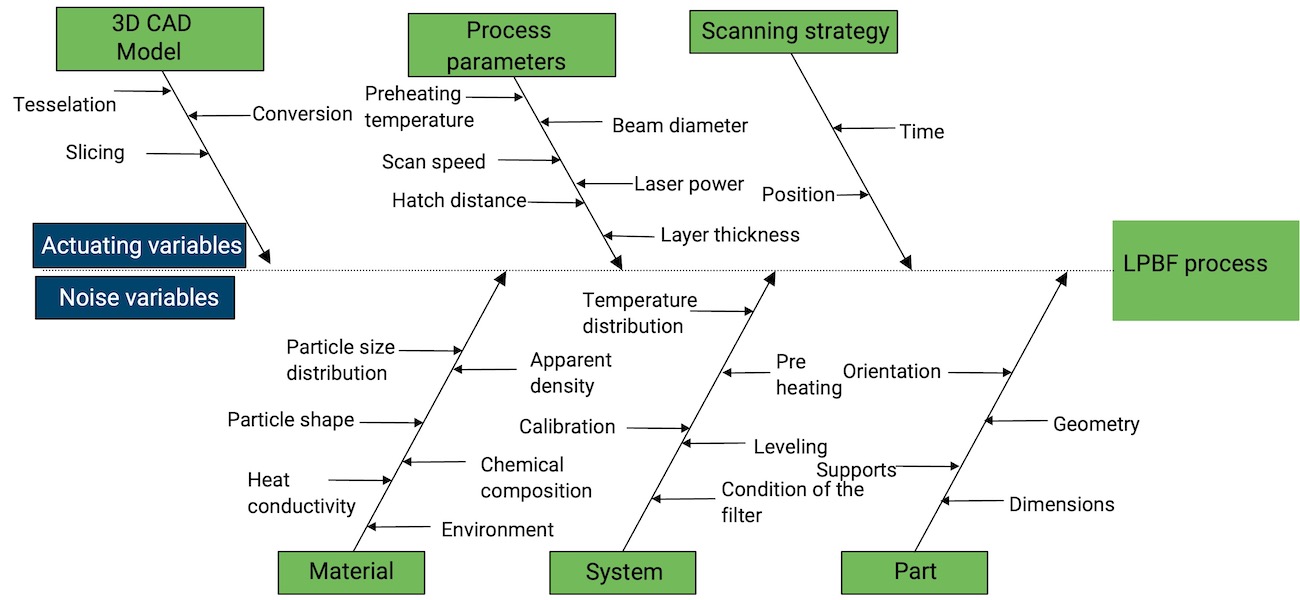
The L-PBF process allows users to control and change approximately 100 process parameters that all have an influence on the final part quality. The fact that these parameters influence each other makes selecting the right parameter complex. The graph displays some of the most important influencing factors of the L-PBF process. We separate them into actuating variables and noise variables. Actuating variables are used to actively influence the melting process and are typically adjusted when developing or optimizing a parameter for a new material. Noise variables, on the other hand, also have an influence on the part quality but are rather controlled to keep a constant result..  

In this section we will focus on the process parameters that are typically adjusted to optimizing the melting of a new material. These parameters are typically expressed in a resulting Volumetric Energy Density (VED), which is defined as

Laser power

Laser power to define meltpool size and productivity

The laser power affects the melting and solidification behavior of the metal powder, as higher power will result in a larger melt pool and a deeper penetration depth. It can also affect the cooling rate of the melted metal, leading to changes in the microstructure and mechanical properties of the final part. Larger melt pools can be advantageous for larger parts or thicker layers, but can also lead to thermal distortion and reduced resolution.

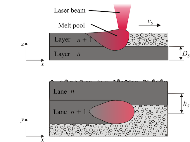
The image shows a schematic illustration of the melt pool during the L-PBF process. The melt pool dynamics are crucial to the overall quality and mechanical properties of the final product. The dynamics refer to the physical and thermal processes that occur within the melt pool, such as fluid flow, solidification, and heat transfer.

The temperature in the melt pool can reach up to several thousand degrees Celsius, and the cooling rate can be extremely high, leading to complex thermal gradients and solidification patterns. The speed and direction of the laser beam, the laser power, and the material properties all affect the melt pool dynamics.

The melt pool dynamics can also affect the microstructure and mechanical properties of the final product. For example, if the cooling rate is too high, it can cause cracking and residual stresses in the material. On the other hand, if the cooling rate is too low, it can lead to the formation of defects such as pores and inclusions.

Source: Eric Wycisk

Scan speed

Scan speed in combination with laser power the most important factor

The combination of scan speed and laser power is the most important parameter combination for a robust welding process. Selecting the right combination will lead to a  continuous and stable weld seam, minimized spatter and an increased productivity.The energy density, which is defined as laser power divided by the spot area, is typically the first factor that needs to be considered when developing a new parameter for a given material. 


Image source: Ruidi Li, Sentral South University

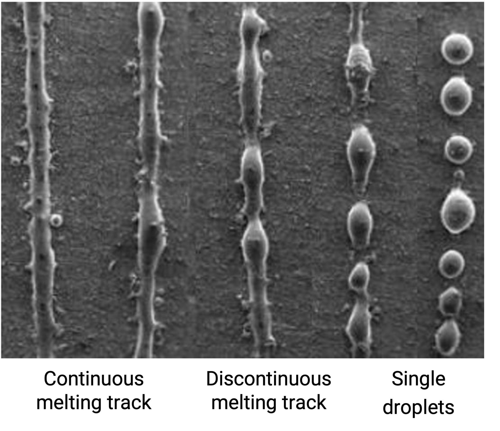
The picture on the left shows that when reducing the energy density, the weld seam first turns into a discontinuous melting track and finally results in single droplets on the right side. This so called balling effect will ultimately lead to defects such as porosity, micro cracks or poor surface finish.

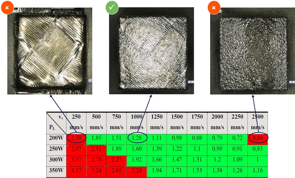
The right picture shows the surface of 3 cubes that were produced in the same material with different energy densities. The cube in the middle, which was produced with a VED of 1.28, shows an even microstructure. The laser lines are still visible and were following a so-called “chessboard” scanning strategy that is often used to increase temperature homogeneity. The cube on the left, which was build with an equal laser power of 200W but a lower scan speed of 200 mm/s had a too high VED of 2.38.This led to a

The cube on the right was built with a laser powder of 200W and a scan speed of 2 500 mm/s and thus a too low VED of 0,66. This led to a lack of fusion and ultimately a rough surface and high porosity. 

Microstructure for 3 different Volumetric Energy Densities of the LPBF process

Layer thickness

Layer thickness as the most effective way to increase productivity

Illustration of the LPBF process and layer thickness Image source: C. Over

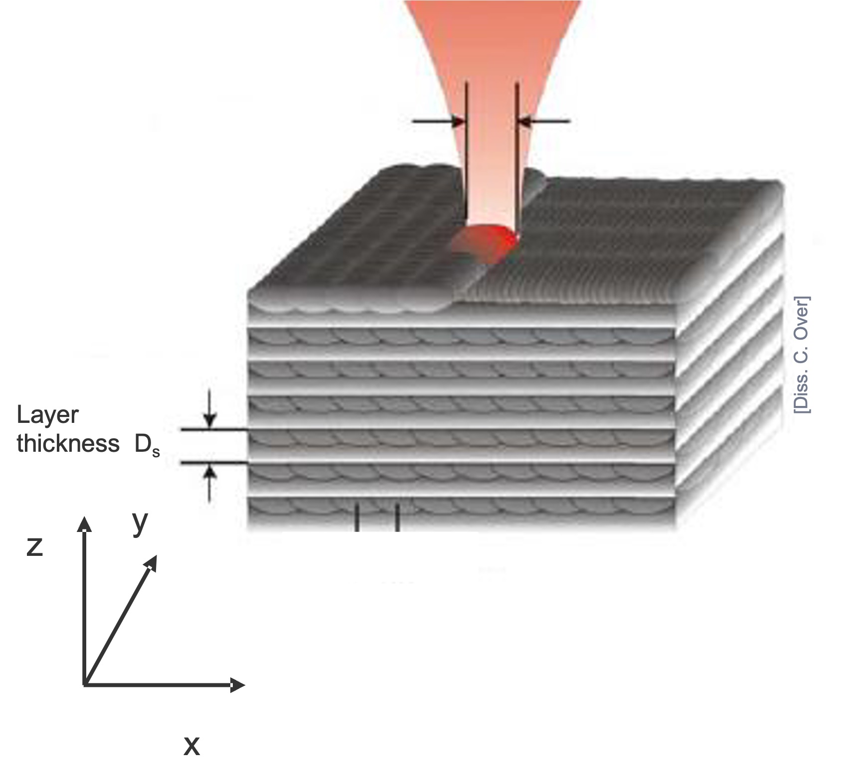
The layer thickness is the most effective way to increase productivity in the LPBF process. Doubling the layer thickness will cut the print time nearly in half and thus has a huge impact on the cost per part. Besides productivity, another positive effect are typically  less residual stresses. On the downside, a higher layer thickness typically also comes with an  increased surface roughness and a lower detail accuracy. The effect on the mechanical properties is complex and cannot generally be defined.

Residual stresses

Residual stresses as the main risk during the LPBF process

Parameters influencing residual stresses: stress inducing mechanisms

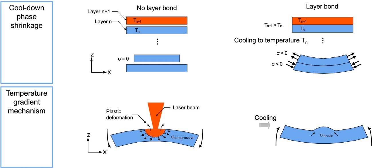
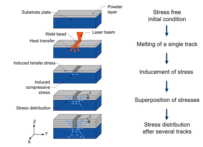
Residual stresses are stresses that remain in a material even after the external loads or thermal loads have been removed. In the context of the L-PBF process, residual stresses can be generated due to the complex thermal interactions that occur during the process.

During the L-PBF process, the material is heated and melted by the laser and then rapidly cooled and solidified, which can create temperature gradients and thermal stresses. Additionally, the successive layers of material can induce thermal expansion and contraction, leading to additional residual stresses. These residual stresses can affect the dimensional accuracy, mechanical properties, and fatigue behavior of the final product.

The magnitude and distribution of the residual stresses in L-PBF depend on various factors, such as the laser power, scanning speed, layer thickness, material properties, and the cooling rate

Principle of forming of residual stresses in layer-wise manufacturing processes

To mitigate the impact of residual stresses on the final product, various strategies can be employed such as post processing treatments (e.g., heat treatment, shot peening) to relieve the stresses, optimizing the process parameters to reduce the stress generation, and improving the design of the product to reduce stress concentrations.

Another strategy to lower residual stresses that is often used is to preheat the powder during the build process. This will both decrease the temperature gradient and also lower the cooling speed. Most industrial systems today are equipped with based plate heating capabilities of around 200°C and first systems come up that use different strategies to heat up the powder to even higher temperatures. 

Scan strategy

Scan strategy with a great potential to further reduce residual stresses

Image source: Jamasp Jhabvala, EPF Lausanne

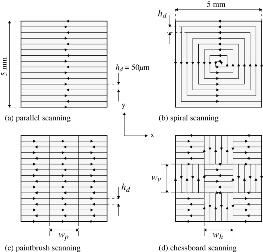
The scan strategy refers to the pattern and direction of laser scanning during the L-PBF process. The graphic on the left displays some common scan strategies that are used to melt the material.

The arrows depict one laser vector. These strategies have partially been deducted from the welding process. The goal of the scan strategy is to achieve a homogenous temperature distribution, ultimately leading to the a stress reduction. Optimizing the scan strategy becomes more complex for multi-laser machines. It must be noted that scan strategies are often known under various synonyms, e.g. paintbrush scanning is often also referred to as stripe scanning.

More recently, several machine suppliers such as VELO3D, SLM SOLUTIONS, and EOS released process parameters to reduce the need for support structures. This can be achieved by editing process parameters such as laser power, scan speed, hatch distance to generate a different downskin energy. 

Gas flow

Gas flow with a big impact on process stability

VTT Technical Research Centre of Finland

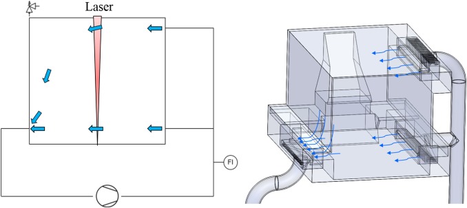
The gas flow is another important factor on the melting process. The goal is to create a homogenous, lamellar gas flow to ensure a stable welding process. The gas flow fulfils several functions: First it is used to constantly transport away the spatter and smoke that occurs during the melting process. Second, it is used to protect the shielding glass and optical system. An inhomogeneous gas flow shows a large influence on the material quality and will lead to increased porosity and surface roughness.

Sinter-based AM technologies and process chain

Sinter-based AM - a technology overview

Many different printing technologies - one sintering process

The sinter-based AM (SBAM) technologies have, as the name suggests, the sintering process in common. In this process, the printed green part is consolidated into a dense part and receives its final properties. The green part can be printed in advance using different technologies.They all have in common that metal powder is bound to the desired shape by a binder. The best-known printing technologies include Binder Jetting and Filament Material Extrusion.

In this section, you learn everything about the sinter-based AM  process chain and get an overview of the different printing technologies.

Goal and structure of this course

This course is aimed at engineers, designers and other professionals that are working closely with sinter-based AM technologies. The goal is to cover the most important aspects that will enable engineers and designers to fully grasp the capabilities and technical limitations of the printing technologies and the sintering process to succeed in technology selection and part design. Besides going through the course from the beginning until the end, this course can also act as a constant source of knowledge while working on AM projects. 

The course is structured into the following sections.

This section will start with an overview of the sinter-based AM process chain and its printing technologies, followed by a technology deep dive into the most important aspects of the BJT technology, followed by a closer look at the debinding and sintering step also including sintering simulation .

The second section will provide an overview of the different materials that are available as well as part characteristics that can be achieved with the BJT process and typical methods for quality assurance. Finally, several common defects in the BJT process are presented. 

The last section will act as a guideline for designers. Besides generally describing the process when designing for Additive Manufacturing, actionable restrictions and guidelines for the BJT process are provided. The final section will present several design examples from different industries. 

What you will find in this section

Sinter-based AM process chain

From digital model to finished part

Data preparation

Simulation to compensate the deformation during the sintering step, nesting of parts and definition of printing parameters

Printing

Through various printing processes, different feedstocks such as metal powders, filaments, pellets or dispersions are processed into green parts

Unpacking

Unpacking of fragile green parts needs to be done carefully and is typically a manual process.

Debinding

Debinding describes the process of removing the binder which results in a brown part

Sintering

To reach the structural integrity of a metal part, a sinter process is required. The powder particles fuse together to a coherent, solid structure via a mass transport that occurs at the atomic scale driven via diffusional forces.

The brown part shrinks ~13-21 % in each direction.

The process chain of sinter-based technologies differs from other AM Technologies. Especially the post-printing processes (debinding and sintering) are crucial to achieve the intended mechanical properties.

Technology principle

How does Binder Jetting work?

Binder Jetting is a powder based Additive Manufacturing technology in which a liquid polymer binder is selectively deposited onto the powder bed binding the metal particles and forming a green body.

The metal powder is applied to a build platform in a typical layer thickness of 40 µm to 100 µm. Subsequently a modified 2D print head apply a binder selectively onto the powder bed. Depending on machine technology a hardening or curing process of the binder is performed in parallel for each layer and/or at the end of the whole build. During the in-situ curing process a heat source is used to solidify the binder and form a solid polymer – metal powder composite.

Working Principle of Binder Jetting

Afterwards the build platform moves downward by the amount of one layer thickness and a new layer of powder is applied. Again, the liquid binder is deposited and hardened in the required regions of the next layer to form the green body. This process is repeated until the complete part is printed. After the complete printing process is finished the parts have to be removed from the “powder cake” meaning the surrounding loose but densified powder. To improve the removal of the excess powder from the green body often brushes or a blasting gun with air pressure are used.

To create a dense metal part the 3D printed green body has to be post-processed in a debinding and sintering process. Similar to the metal injection molding process BJT parts are placed in a high temperature furnace, where the binder is burnt out and the remaining metal particles are sintered together. The sintering results in densification of the 3D printed green body to a metal part with high densities of 97 % to 99,5%, dependent of the material.

Printing Technologies

Metal Binder Jetting

Binder Jetting is a powder based Additive Manufacturing technology in which a liquid polymer binder is selectively deposited onto the powder bed binding the metal particles and forming a green body.

The metal powder is applied to a build platform in a typical layer thickness of 40 µm to 100 µm. Subsequently a modified 2D print head apply a binder selectively onto the powder bed. Depending on machine technology a hardening or curing process of the binder is performed in parallel for each layer and/or at the end of the whole build. During the in-situ curing process a heat source is used to solidify the binder and form a solid polymer – metal powder composite.

Working Principle of Binder Jetting

Material Extrusion

Binder Jetting is a powder based Additive Manufacturing technology in which a liquid polymer binder is selectively deposited onto the powder bed binding the metal particles and forming a green body.

The metal powder is applied to a build platform in a typical layer thickness of 40 µm to 100 µm. Subsequently a modified 2D print head apply a binder selectively onto the powder bed. Depending on machine technology a hardening or curing process of the binder is performed in parallel for each layer and/or at the end of the whole build. During the in-situ curing process a heat source is used to solidify the binder and form a solid polymer – metal powder composite.

Working Principle of Binder Jetting

Mold Slurry Deposition

Binder Jetting is a powder based Additive Manufacturing technology in which a liquid polymer binder is selectively deposited onto the powder bed binding the metal particles and forming a green body.

The metal powder is applied to a build platform in a typical layer thickness of 40 µm to 100 µm. Subsequently a modified 2D print head apply a binder selectively onto the powder bed. Depending on machine technology a hardening or curing process of the binder is performed in parallel for each layer and/or at the end of the whole build. During the in-situ curing process a heat source is used to solidify the binder and form a solid polymer – metal powder composite.

Working Principle of Binder Jetting

Metal Selective Laser Sintering

Binder Jetting is a powder based Additive Manufacturing technology in which a liquid polymer binder is selectively deposited onto the powder bed binding the metal particles and forming a green body.

The metal powder is applied to a build platform in a typical layer thickness of 40 µm to 100 µm. Subsequently a modified 2D print head apply a binder selectively onto the powder bed. Depending on machine technology a hardening or curing process of the binder is performed in parallel for each layer and/or at the end of the whole build. During the in-situ curing process a heat source is used to solidify the binder and form a solid polymer – metal powder composite.

Working Principle of Binder Jetting