Powder DED Material Properties & Defects
Material Properties and Defects
Benchmarking Powder DED Technologies: Measured Capabilities from Real Parts
This section highlights the typical material properties and defects of Powder Laser Energy Deposition and Cold Spray, based on the production and analysis of multiple demonstrator components. Several machine OEMs contributed parts, which were evaluated in detail for density, surface quality, and tensile strength. In total, six components were analyzed: four produced with Laser Powder DED and two with Cold Spray.
What you will learn in this section
Understand the Capabilities of Powder DED Technologies
Explore how different technologies perform across build rate, surface waviness, minimum wall thickness, and more—based on measured data.
Learn How Performance Trade-Offs Shape Part Quality
See how optimizing for one parameter (like speed) often affects others (like surface quality).
Understand Mechanical Properties of Powder DED
Understand the mechanical properties of Powder DED and how they compare to standard values.
What you will find in this section
Material Properties Laser Powder ED
Powder Laser ED material properties high for simple geometries
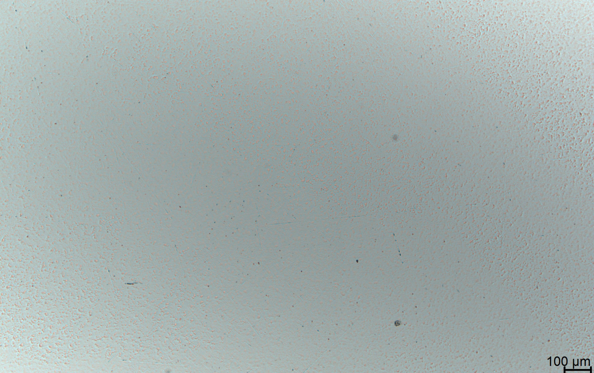
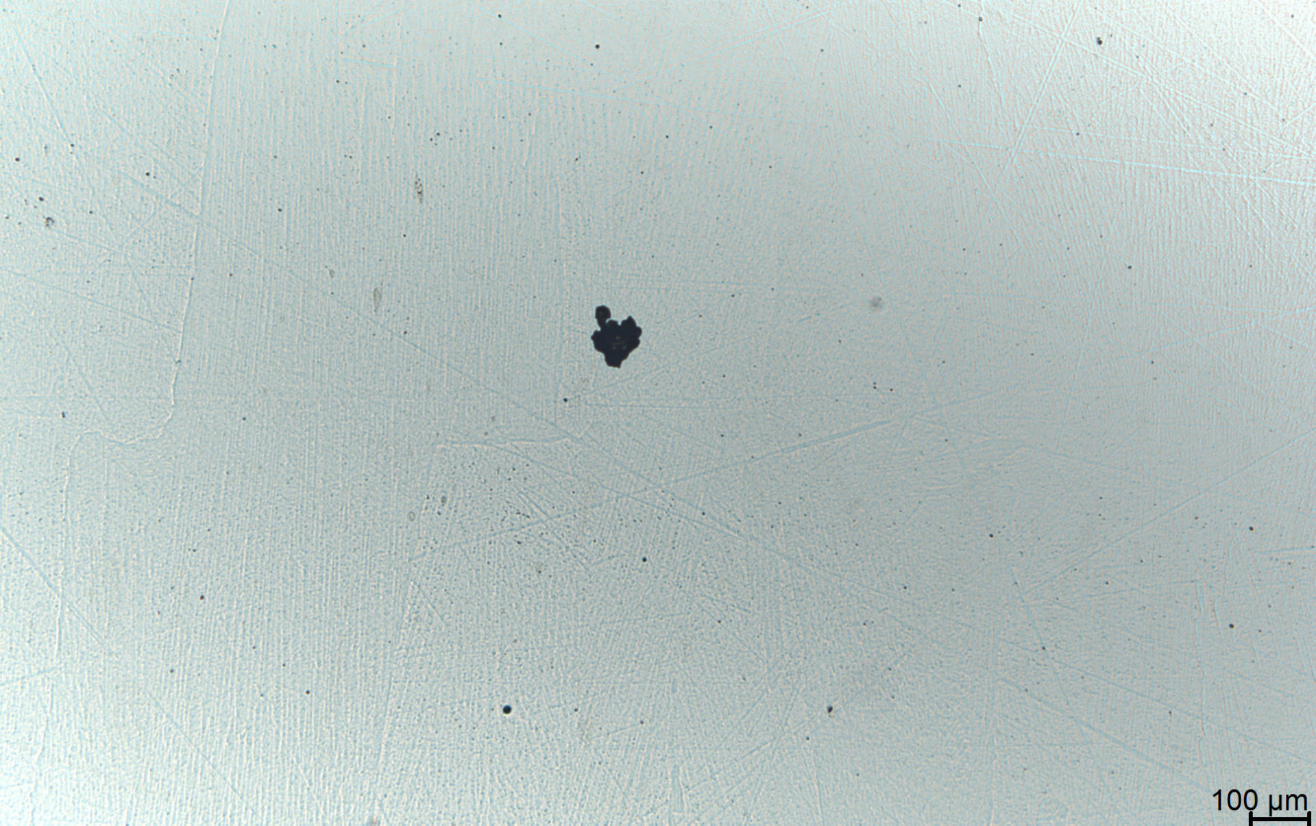
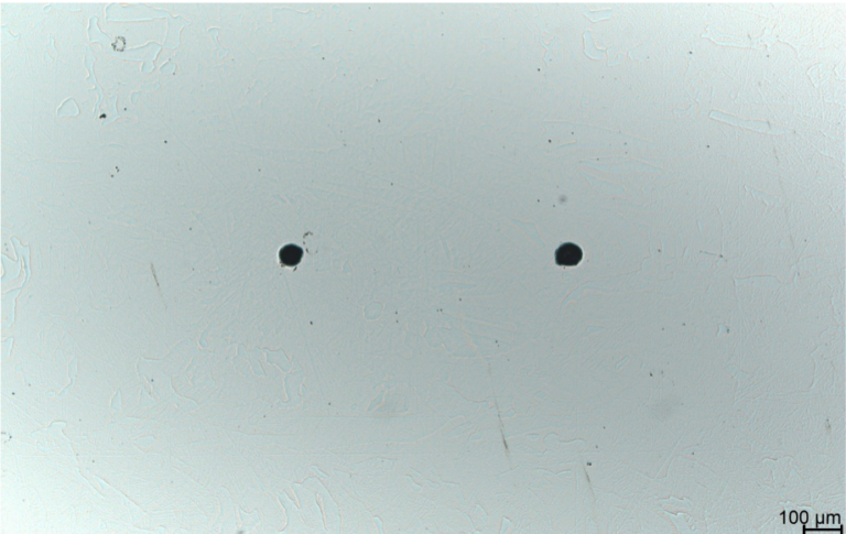
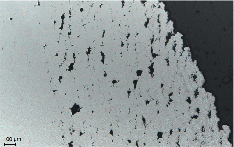
Parts fabricated using Powder Laser Energy Deposition usually show high density of more than 99,9 % and good mechanical properties. In the left micrograph, a typical cross-section of a Powder Laser Deposition component is displayed. Apart from gas porosity in the micrometer range, no larger defects are visible. The right the micrograph exhibits a larger pore which results from process instabilities. The density mainly depends on the heat input, the powder feed rate and the 3D toolpath. In a well-controlled Powder Laser Deposition process larger pores are rather exceptional.
For the resulting microstructure, the temperature gradient during part fabrication is decisive. The temperature gradient in turn depends strongly on the part’s geometry as well as the scanning strategy and cooling breaks during manufacturing. Most commonly a directed growth of long grains towards the cooling direction occurs. Occasionally a globular microstructure can be observed in thin-walled parts.
Typical material properties for as built 316L in Powder Laser ED
Some typical material properties for the stainless steel 316L are shown in the diagrams. All tensile values of the Powder Laser ED specimens exceed the required norm values defined in ASTM A276 (Standard Specification for Stainless Steel Bars and Shapes) except for the elongation in horizontal direction.
A strong anisotropy of mechanical properties can be observed. Yield strength and ultimate tensile strength are higher in horizontal direction (perpendicular to the building direction) than in building direction. In turn, vertically oriented test specimens exhibit higher ductility. The anisotropy can be attributed to two effects. First the directed grain growth results in a strong texture of the microstructure which causes anisotropic properties. Secondly, the cooling of horizontal test bars is faster due to their larger connection area with the base plate. The faster cooling creates a finer microstructure in the horizontal test coupon compared to the vertical coupon. The fine microstructure results in higher strength and less ductility.
Material Properties Cold Spray
With heat treatment Coldspray material properties similar to bulk material
Parts fabricated using Coldspray technology normally have lower mechanical properties when compared to bulk material. By applying heat treatments properties are homogenized and result in mechanical characteristics similar to bulk materials.
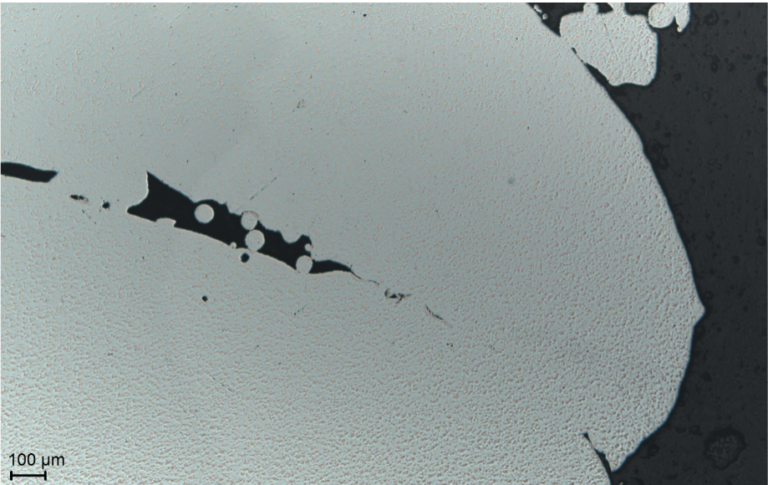
The decrease of mechanical properties is caused by defects such as micro-pores and inter-particle boundaries that can be typically found in Coldspray deposits. These defects are caused by insufficient particle plastic deformation and poor inter-particle bonding during deposition. Defects act as structural weaknesses and lower, amongst other, the ductility, strength and modulus. In return, the hardness of Coldspray parts is usually higher due to the work hardening process occurring during the impacts between particles and substrate.
Typical cross section in Stainless Steel 17-4PH printed with Cold Spray
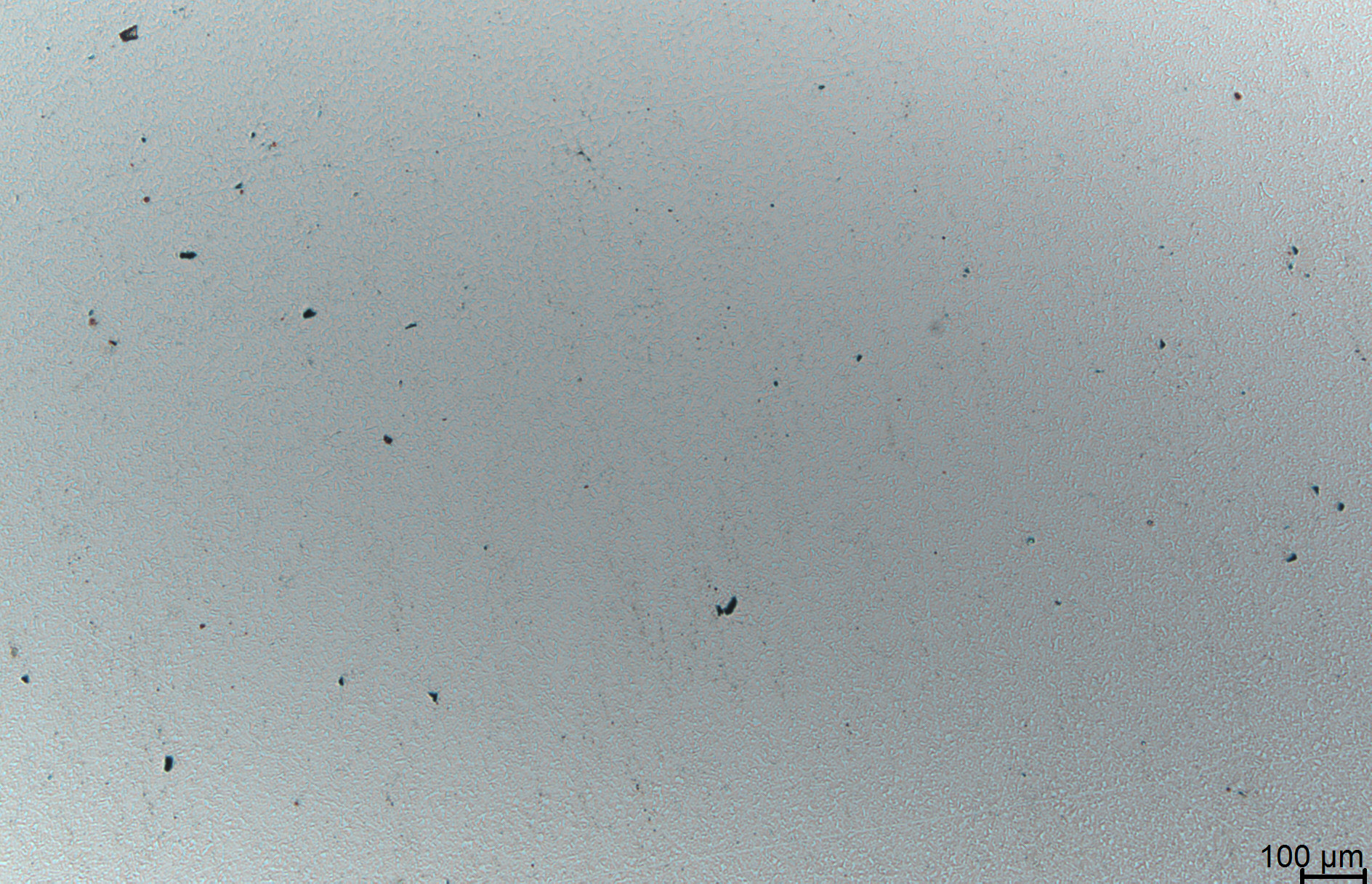
Micro-pores and inter-particle boundaries that can be typically found in coldsprayed deposits
Porosity and Bonding Defects
Invisible Voids with Visible Consequences
Porosity refers to spherical or elongated voids formed by trapped gas during the solidification of the printed metal. While a certain level of porosity is typical for Powder DED technologies, certain parts can show significant imperfections.
These imperfections can result from inadequate process parameters or feedstock characteristics. Porosity may present as uniformly distributed gas pores or as clustered accumulations. While most gas pores are round, elongated voids can also occur due to melt pool instability. These defects can be embedded within the part or appear as visible surface pores, compromising both mechanical properties and part density.
Typical causes of porosity and bonding defects
Insufficient Energy Input
Insufficient Energy Input
Excessive Material Feed Rate
Excessive Material Feed
High Energy Input
High Energy Input
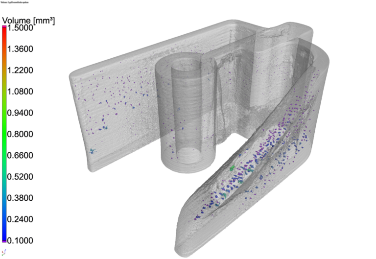
Porosity and bonding defects can occur in different regions of printed parts. The images below show CT scans of two examples: one produced with Cold Spray and the other with Powder Laser ED.
The Powder Laser ED part demonstrates a very high overall density of 99.95%, with only small pores distributed throughout the part. A localized pore agglomeration is visible in the angled wall feature, likely caused by an unstable 5-axis weld path during manufacturing.
In contrast, the Cold Spray part on the left exhibits a density of 99.72%, with larger defect accumulations observed at edges and turning points. These are attributed to the start/stop behavior of the nozzle and the 5-axis spray operation, both of which affect particle impact and bonding quality.
Porosity in printed part in Aluminium (Cold Spray)
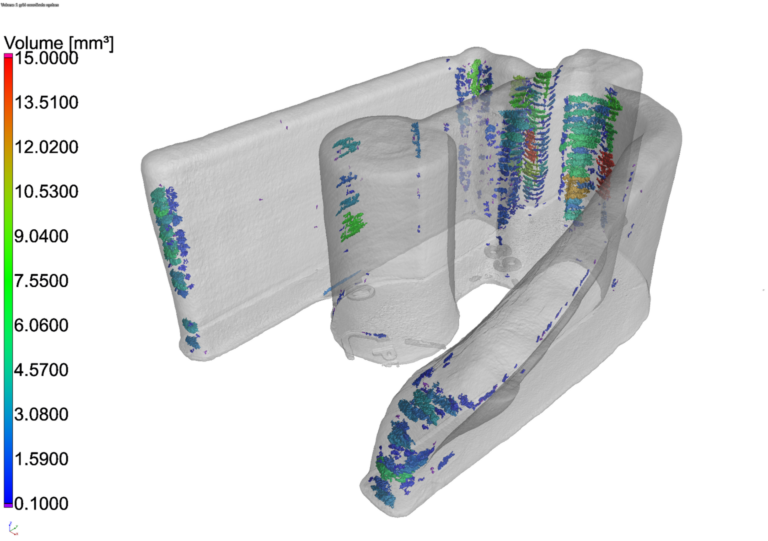
Porosity in printed part in SS 316L (Powder Laser ED)
