Cost comparison Valve Block old

Cost comparison valve block

What are production costs for the valve block?

This case study breaks down the production cost of a valve block for suitable technologies. Besides a breakdown of the total cost per part, the manufacturing time and cost per volume for different production quantities is provided. 

Valve Block overview

Valve block not feasible for DED

The technologies considered for the valve block are Metal Binder Jetting, Powder Bed Fusion and Metal ME. Due to dimensions of 30 x 15 x 60 mm and a total part volume of 7,5 cm³, the part is not feasible for Laser Metal Deposition (LMD) and Wire Arc Additive Manufacturing (WAAM) technologies which are thus excluded from this comparison. The calculation is made for Stainless Steel 17-4PH, which is available for all technologies. The calculation is made for 100 parts with a comparison of 10 parts and 1 000 parts at the end.

The focus in this section lies exclusively on the cost comparison. The fact that the achievable part quality varies between the technologies must be kept in mind.

The following post processing operations are included in the calculation:

  • Unloading and unpacking of parts (All technologies)
  • Heat Treatment (L-PBF)
  • Part separation (L-PBF)
  • Support Removal (L-PBF, E-PBF, ME)
  • Debinding (ME)
  • Sintering (BJT and ME)

Cost per part

Binder Jetting with lowest cost per part

Comparison of in-house manufacturing cost for the valve Block for different technologies

Binder Jetting is the most cost-effective technology for producing this part for a series of 100 parts. The main difference results from low process-costs of ~5 €. These low costs can be achieved by producing all 100 parts in less than 15 hours on a medium-sized system. The 10 € post processing cost result from unpacking and sintering.

Laser and Electron Beam Powder Bed Fusion have similar cost per part of ~43 €. The thin walls make the part challenging for EPBF.

Material Extrusion results in the highest cost for this part. This is mainly driven by the long printing time of over 5 hours per part.

The corresponding relative breakdown of costs shows that for both Powder Bed Fusion technologies, the build process makes up the majority of the costs with 59%.

For Metal Binder Jetting, the low process costs result in post processing cost of 59%, which is mainly driven by the sinter and unpacking cost.

For Metal Extrusion, 75% of all cost result from the printing process. This is due to the long production time that can be seen in the next paragraph.

Comparison of the relative in-house manufacturing cost for the Valve Block for different technologies

Production time

Binder Jetting with very low printing time but higher effort for sintering

Production Time Comparison for the different technologies for the Valve Block

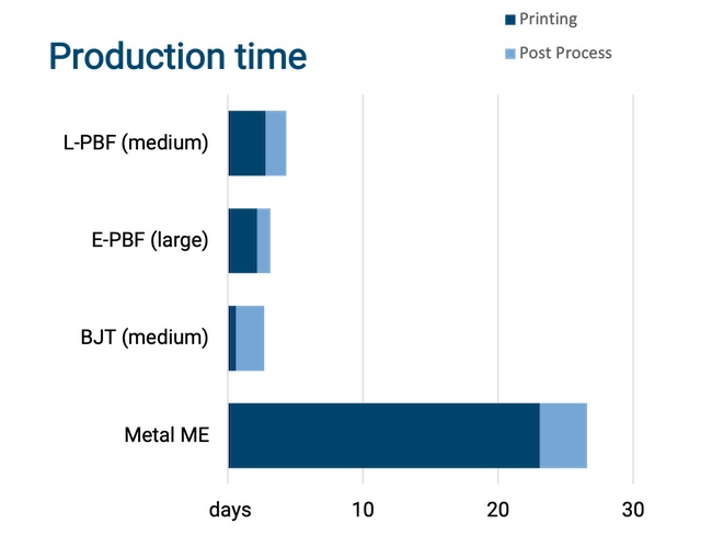
The chart on the left breaks down the production time in days for the entire batch of 100 parts into the following sub-processes:

  • Process: includes data preparation, machine setup and printing
  • Post processing: includes support removal, debind and sintering and other operations

Binder Jetting shows the lowest printing time with ~15 hours for all parts, compared to ~2,5 days for PBF and ~23 days for Material Extrusion. Taking into account post processing, Binder Jetting still keeps the lowest production time of ~2,5 days compared to over 3 days for E-PBF,  ~4,5 days for L-PBF and ~27 days for Metal Extrusion.
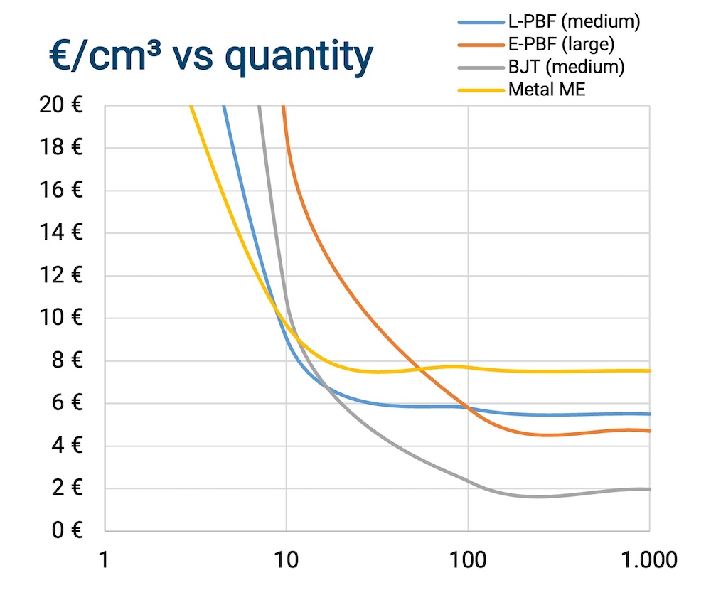
Cost per cm³

Strong cost decrease for higher production volumes

The right graph shows the corresponding cost per cm³ for quantities ranging from 10 to 1000 parts. While Binder Jetting is the most cost effective technology for the 100 parts discussed in this scenario, lower quantities favour other technologies.

When printing a fewer than 8 pieces, Metal FDM is the cheapest technology since it is not a batch-wise process. For quantities between 8 and 15 pieces, Laser Powder Bed Fusion is the most cost-effective technology. 

With Electron Beam Powder Bed Fusion, the parts could be stacked on top of each other, resulting in several 100 parts in one build job. This makes the technology cheaper compared to L-PBF for volumes >100 parts.

As soon as the quantity results in a reasonable nesting density of the build job, which in this case is starting from 15 parts,  Binder Jetting remains the cheapest technology.

Breakdown of the cost per cm³ for the Valve Block
Sinter-based AM technologies and process chain

Sinter-based AM - a technology overview

Many different printing technologies - one sintering process

The sinter-based AM (SBAM) technologies have, as the name suggests, the sintering process in common. In this process, the printed green part is consolidated into a dense part and receives its final properties. The green part can be printed in advance using different technologies.They all have in common that metal powder is bound to the desired shape by a binder. The best-known printing technologies include Binder Jetting and Filament Material Extrusion.

In this section, you learn everything about the sinter-based AM  process chain and get an overview of the different printing technologies.

Goal and structure of this course

This course is aimed at engineers, designers and other professionals that are working closely with sinter-based AM technologies. The goal is to cover the most important aspects that will enable engineers and designers to fully grasp the capabilities and technical limitations of the printing technologies and the sintering process to succeed in technology selection and part design. Besides going through the course from the beginning until the end, this course can also act as a constant source of knowledge while working on AM projects. 

The course is structured into the following sections.

This section will start with an overview of the sinter-based AM process chain and its printing technologies, followed by a technology deep dive into the most important aspects of the BJT technology, followed by a closer look at the debinding and sintering step also including sintering simulation .

The second section will provide an overview of the different materials that are available as well as part characteristics that can be achieved with the BJT process and typical methods for quality assurance. Finally, several common defects in the BJT process are presented. 

The last section will act as a guideline for designers. Besides generally describing the process when designing for Additive Manufacturing, actionable restrictions and guidelines for the BJT process are provided. The final section will present several design examples from different industries. 

What you will find in this section

Sinter-based AM process chain

From digital model to finished part

Data preparation

Simulation to compensate the deformation during the sintering step, nesting of parts and definition of printing parameters

Printing

Through various printing processes, different feedstocks such as metal powders, filaments, pellets or dispersions are processed into green parts

Unpacking

Unpacking of fragile green parts needs to be done carefully and is typically a manual process.

Debinding

Debinding describes the process of removing the binder which results in a brown part

Sintering

To reach the structural integrity of a metal part, a sinter process is required. The powder particles fuse together to a coherent, solid structure via a mass transport that occurs at the atomic scale driven via diffusional forces.

The brown part shrinks ~13-21 % in each direction.

The process chain of sinter-based technologies differs from other AM Technologies. Especially the post-printing processes (debinding and sintering) are crucial to achieve the intended mechanical properties.

Technology principle

How does Binder Jetting work?

Binder Jetting is a powder based Additive Manufacturing technology in which a liquid polymer binder is selectively deposited onto the powder bed binding the metal particles and forming a green body.

The metal powder is applied to a build platform in a typical layer thickness of 40 µm to 100 µm. Subsequently a modified 2D print head apply a binder selectively onto the powder bed. Depending on machine technology a hardening or curing process of the binder is performed in parallel for each layer and/or at the end of the whole build. During the in-situ curing process a heat source is used to solidify the binder and form a solid polymer – metal powder composite.

Working Principle of Binder Jetting

Afterwards the build platform moves downward by the amount of one layer thickness and a new layer of powder is applied. Again, the liquid binder is deposited and hardened in the required regions of the next layer to form the green body. This process is repeated until the complete part is printed. After the complete printing process is finished the parts have to be removed from the “powder cake” meaning the surrounding loose but densified powder. To improve the removal of the excess powder from the green body often brushes or a blasting gun with air pressure are used.

To create a dense metal part the 3D printed green body has to be post-processed in a debinding and sintering process. Similar to the metal injection molding process BJT parts are placed in a high temperature furnace, where the binder is burnt out and the remaining metal particles are sintered together. The sintering results in densification of the 3D printed green body to a metal part with high densities of 97 % to 99,5%, dependent of the material.

Printing Technologies

Metal Binder Jetting

Binder Jetting is a powder based Additive Manufacturing technology in which a liquid polymer binder is selectively deposited onto the powder bed binding the metal particles and forming a green body.

The metal powder is applied to a build platform in a typical layer thickness of 40 µm to 100 µm. Subsequently a modified 2D print head apply a binder selectively onto the powder bed. Depending on machine technology a hardening or curing process of the binder is performed in parallel for each layer and/or at the end of the whole build. During the in-situ curing process a heat source is used to solidify the binder and form a solid polymer – metal powder composite.

Working Principle of Binder Jetting

Material Extrusion

Binder Jetting is a powder based Additive Manufacturing technology in which a liquid polymer binder is selectively deposited onto the powder bed binding the metal particles and forming a green body.

The metal powder is applied to a build platform in a typical layer thickness of 40 µm to 100 µm. Subsequently a modified 2D print head apply a binder selectively onto the powder bed. Depending on machine technology a hardening or curing process of the binder is performed in parallel for each layer and/or at the end of the whole build. During the in-situ curing process a heat source is used to solidify the binder and form a solid polymer – metal powder composite.

Working Principle of Binder Jetting

Mold Slurry Deposition

Binder Jetting is a powder based Additive Manufacturing technology in which a liquid polymer binder is selectively deposited onto the powder bed binding the metal particles and forming a green body.

The metal powder is applied to a build platform in a typical layer thickness of 40 µm to 100 µm. Subsequently a modified 2D print head apply a binder selectively onto the powder bed. Depending on machine technology a hardening or curing process of the binder is performed in parallel for each layer and/or at the end of the whole build. During the in-situ curing process a heat source is used to solidify the binder and form a solid polymer – metal powder composite.

Working Principle of Binder Jetting

Metal Selective Laser Sintering

Binder Jetting is a powder based Additive Manufacturing technology in which a liquid polymer binder is selectively deposited onto the powder bed binding the metal particles and forming a green body.

The metal powder is applied to a build platform in a typical layer thickness of 40 µm to 100 µm. Subsequently a modified 2D print head apply a binder selectively onto the powder bed. Depending on machine technology a hardening or curing process of the binder is performed in parallel for each layer and/or at the end of the whole build. During the in-situ curing process a heat source is used to solidify the binder and form a solid polymer – metal powder composite.

Working Principle of Binder Jetting