characteristics of metal L-PBF
Mechanical characteristics
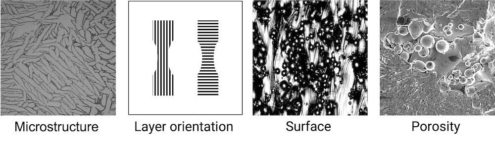
Microstructure, layer orientation, surface and porisity
aaa
What you will find in this section
Microstructure
aaa
aaa
Surface
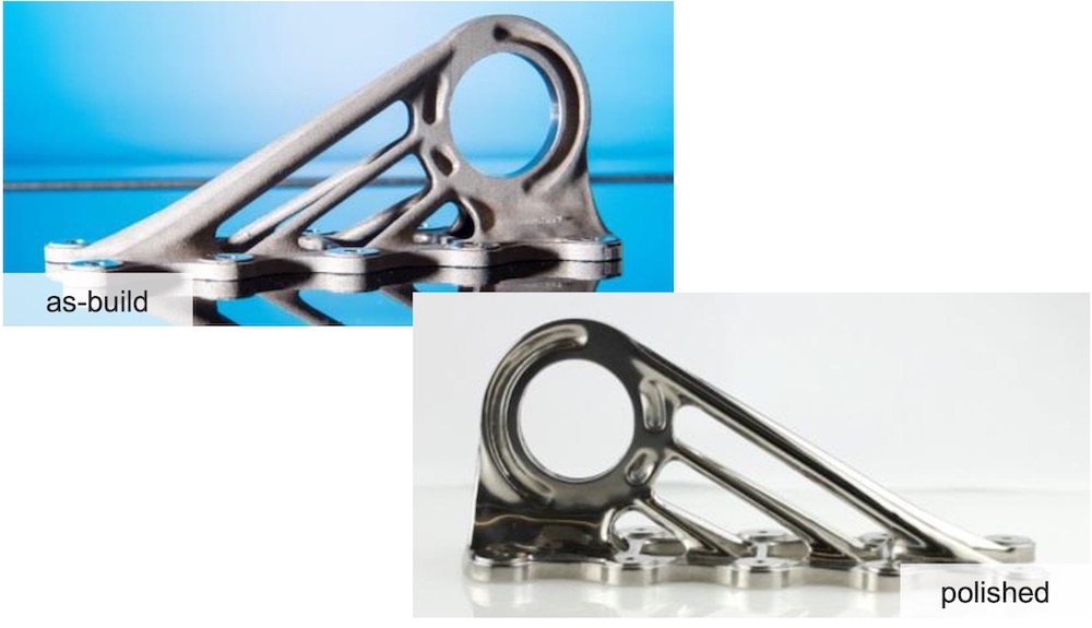
Grainy surface finish as printed
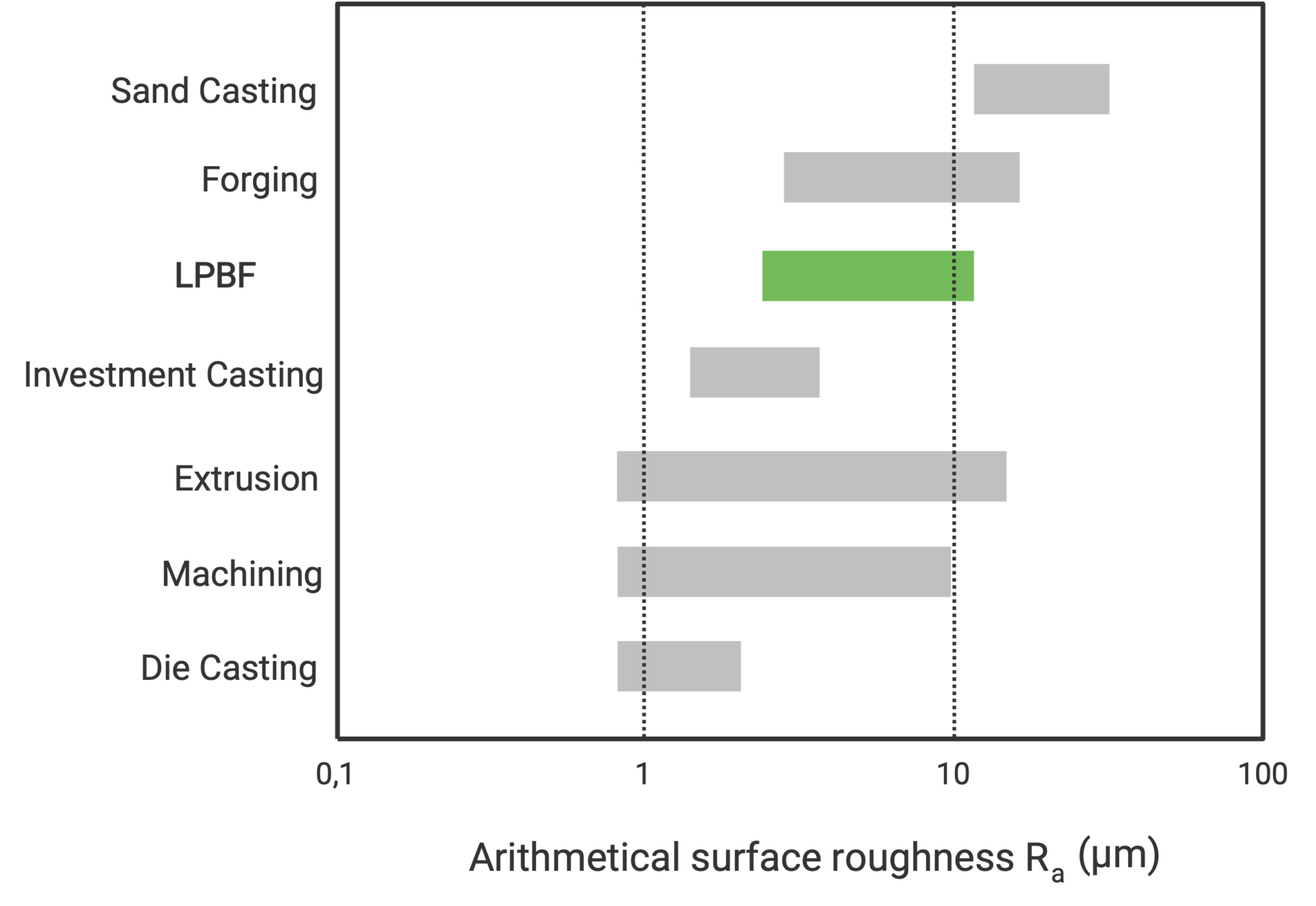
Parts produced with LPBF show a grainy, rough surface after printing. The graph above compares the typical surface roughness of several technologies. LPBF typically lies between investment casting and forging. The achievable roughness strongly depends on the layer thickness, powder size, surface orientation, process parameters and focal diameter.
As a rule of thumb, the as-printed surface roughness is Rz: 80 – 140 µm and Ra: 5 – 15 µm. While different values can be achieved for different orientations, downward-facing surfaces usually display the highest roughness.
For small layer thicknesses, high process resolution in combination with small powder particle distribution results in a smoother surface. For the opposite, large layer thicknesses, low resolutions and coarse powder particles, a high surface roughness is expected. A high surface roughness can be desired in some cases, for example in medical applications, where it facilitates bone ingrowth.
The final part surface has a large impact on the functional properties and its use. Design considerations should not only be focused on the printing process. It also needs to be considered when it comes to decide on post-processing steps and how to perform these on the printed part. The as-built quality of the printing process influences the type and extent of post surface treatment.
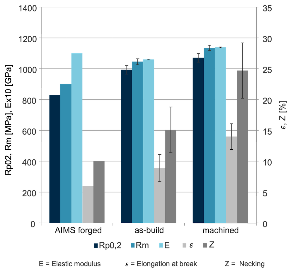
The chart on the right compares static mechanical properties of parts printed in Ti-Al6-V4 in forged, as build and machined condition. First it can be seen that both as printed and machined values exceed the properties that can be achieved with forging. Second, the as-build surface roughness has little influence on yield and ultimate tensile strength.
The elongation at break and reduction of the area reduces significantly due to high surface roughness.