Data Preparation
Data Preparation
CAD, CAM and CNC Control Software
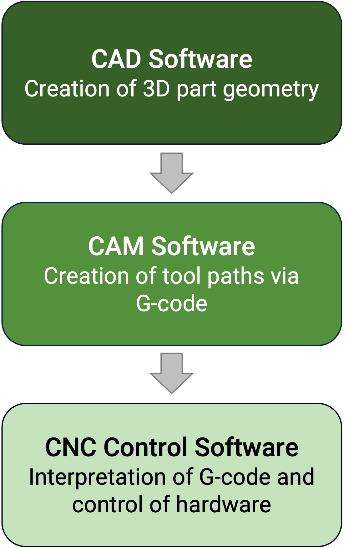
The Powder DED process workflow begins with CAD software, where the 3D part geometry is created and manipulated. This step includes tasks such as creating offsets, simplifying complex features, and filling holes to prepare the model for manufacturing. Once the design is finalized, the geometry is exported in a compatible format, depending on the CAD-CAM software used, ensuring seamless integration into the next step of the process.
The second step involves CAM software, which is used to generate tool paths and CNC programs, typically in G-code, to describe the motion and operations of the DED system. The specific software and coding requirements depend on the type of handling system, such as a robotic arm, portal system, or machine tool. The programming effort can vary significantly based on the capabilities and support provided by the CAM software, which directly impacts the efficiency of the tool path generation process.
Finally, the CNC control software interprets the G-code and controls the DED hardware during operation. This software ensures the accurate execution of the programmed tool paths and may interface with additional control systems, such as triggering the laser source and powder feeder. Precise coordination of these systems is critical for producing high-quality parts, making this final step essential for successful DED process execution.

Computer Aided Manufacturing (CAM)
Complex data preparation compared to other metal AM technologies

Generating the tool paths and CNC program to build the geometries forms the key step of the data preparation phase. It consists of the following 5 steps:
- Dividing part geometry
- Creating center planes
- Defining tool path for geometrical
- Simulation of tool paths features
- Collision simulation of whole system
Dividing part geometry & Creating center planes
The process begins with selecting the manufacturing system. A predefined machine body and axis configuration are chosen to suit the specific part requirements. This ensures that the chosen system can effectively handle the part geometry and manufacturing process.
Once the system is selected, the part geometry is imported into the CAM module. This step integrates the 3D model into the software environment, enabling further manipulation and preparation for manufacturing.
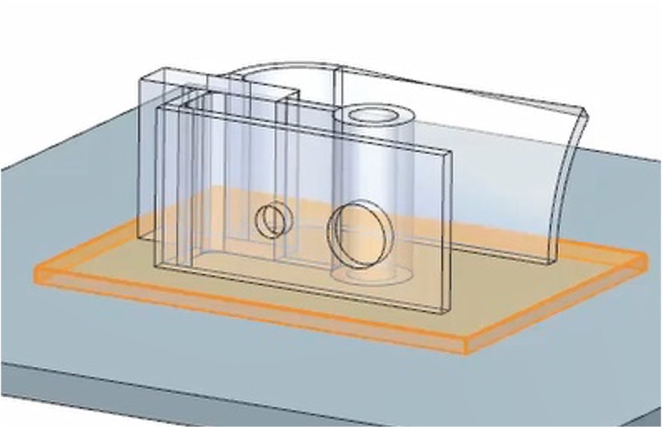
The next step involves the definition of the AM part and base plate geometry. This is where the shapes and dimensions of the part and its supporting structures are precisely determined, ensuring stability during the manufacturing process.
The dividing of part geometry into features follows, where specific sections such as thin walls, cylinders, or voluminous areas are identified. This segmentation is essential to optimize the manufacturing approach for each unique feature.
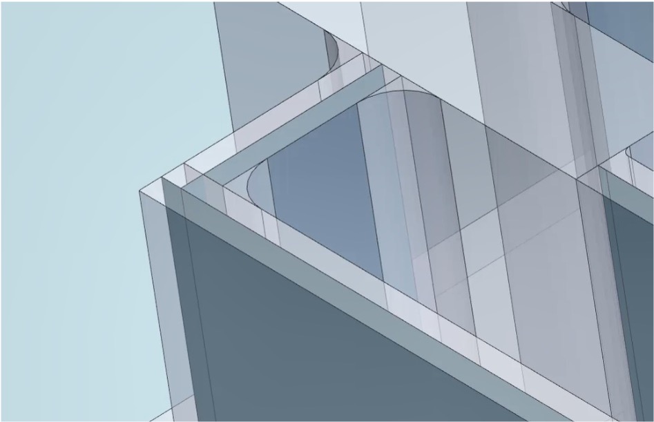
Finally, center planes are created for wall features, allowing for efficient programming. These center planes enable either single-path or multi-path strategies with offset programming, ensuring precise and controlled material deposition for complex wall structures.
Defining tool path for geometrical features
The tool path for weld bead application is programmed in G-Code, which serves as the instruction set for the manufacturing system. The complexity of this programming step can vary significantly depending on the specific system and the level of user support provided by the software.
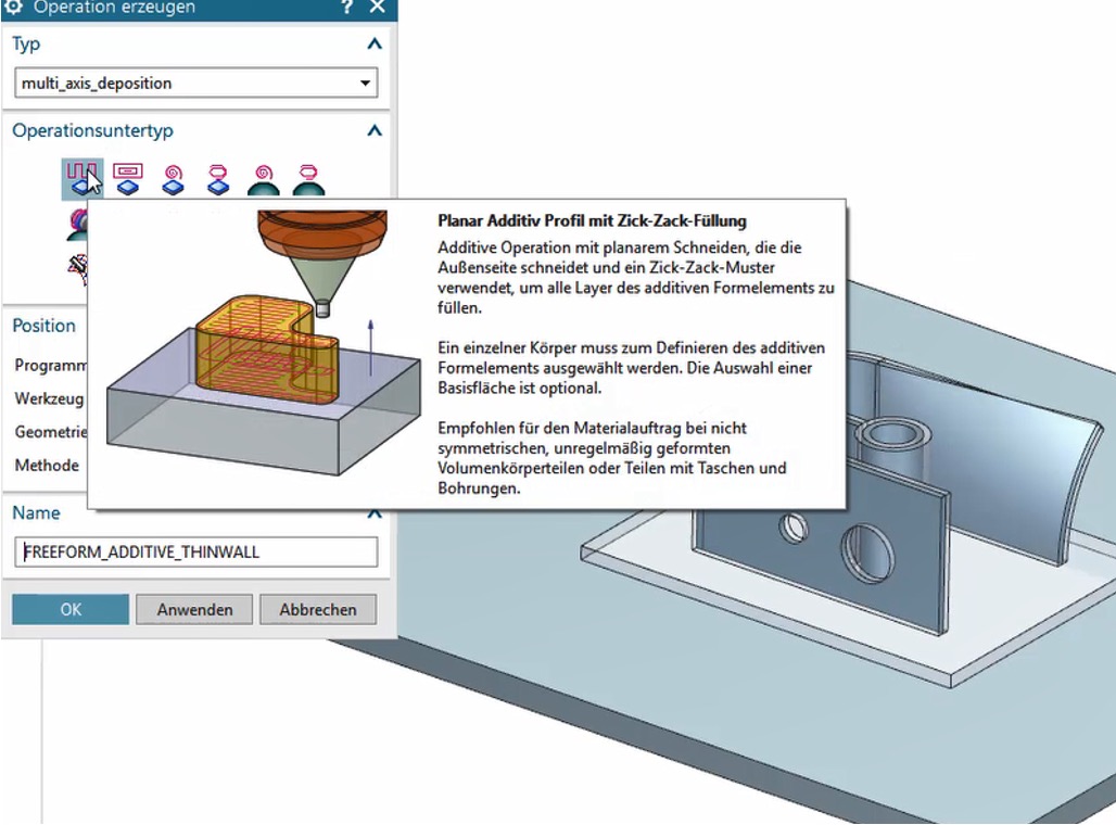
In some cases, users may need to manually program each individual path, requiring meticulous attention to detail and extensive time investment. However, advanced software solutions, such as Siemens NX, offer predefined tool path strategies tailored to different geometrical features. This feature streamlines the programming process and reduces the potential for errors.
To successfully create the underlying process data, deep knowledge of the DED process is essential. This includes understanding the interactions between material, energy, and tool path strategies, ensuring high-quality weld bead application and optimal part performance.

Modern manufacturing systems and CAM software, such as Siemens NX, offer predefined tool path strategies designed for different surface geometries. For flat surfaces and voluminous features, a zig-zag path strategy is typically applied to ensure efficient material deposition. For thinner features, a single-path strategy provides greater precision and control.
When working with complexly curved base materials, specialized strategies are employed to align the tool path with the curvature of the part. This is particularly relevant for geometries like curved tubes, where varying layer thickness must be accounted for during programming.
However, achieving accurate alignment between the programmed tool path and the manufacturing result requires a well-established and stable process. For geometries with varying layer heights, such as curved tubes, the challenge increases due to the complexity of maintaining consistent material deposition. A thorough understanding of the process and its limitations is essential to ensure high-quality outcomes.
Simulating toolpaths and collission checks
Tool Path Simulation and Collision check in Siemens NX
The simulation of tool paths is a critical step in the manufacturing workflow, ensuring the plausibility and proper sequencing of the programmed tool paths. This step allows for the visualization of the deposition process, enabling the identification of potential issues before production begins.
A key aspect of simulation is the collision check, particularly in systems involving 5-axis part and tool manipulation. With the added complexity of multiple axes, the risk of collisions between the tool, part, and machine components increases. Simulation ensures that the tool paths are free of such conflicts, safeguarding both the equipment and the workpiece.
By performing these simulations, manufacturers can optimize the process, reduce errors, and ensure a smooth transition from programming to actual production.
Proprietary Data Preparation Solution for Cold Spray company SPEE3D
Proprietary data preparation software by Spee3D
Proprietary data preparation solutions, such as those used by Speed3D, offer streamlined and user-friendly software comparable to pre-processing steps described above or even comparaed to Laser Powder Bed Fusion. These solutions simplify the workflow, making them accessible even to users with limited prior experience in advanced manufacturing.
A notable feature of these systems is that the tool path calculation is performed on external servers, such as Speed3D’s dedicated platform. While this offloading reduces the computational load on local systems and speeds up processing, it also means that users have no direct access to the underlying tool path know-how. This can limit customization and process understanding, as critical details of the path generation remain proprietary.
Despite these constraints, such solutions are valued for their efficiency and ease of use, especially in environments where rapid setup and deployment are priorities.


