Applications of Additive Manufacturing
From prototyping to spare parts
Additive Manufacturing is used in a wide range of industries. Since its origins as a prototyping technology in the 80s it has come a long way. Today, applications can be found across the entire value chain, from prototyping to spare parts and repair.
We want to give a brief overview of the benefits of using AM in different areas, followed by one case study for each of these areas.
What you will learn in this section
Explore Key Application Areas
Understand how AM is used across five core applications—from prototyping to repair—each with its own value drivers and technology fit.
See Real-World Examples
Discover case studies from leading companies like GE, Liebherr, and Daimler, showing how AM delivers impact across industries.
Identify When to Use AM
Learn how to spot ideal use cases for AM in product development, tooling, end-use production, spare parts, and refurbishment.
What you will find in this section
Applications areas
Where Additive Manufacturing Creates Real Value
Explore five key application areas where AM offers unique advantages in speed, cost, flexibility, and performance.
Prototyping & Product Development
Prototyping & Product Development
Tooling, Jigs & Fixtures
Tooling, Jigs & Fixtures
End-use Parts
End-use parts
Spare Parts
Spare Parts
Repair
Repair
Prototyping
Re-design of an advanced turboprop engine
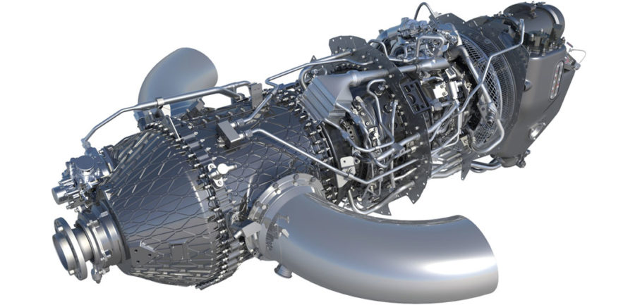
This case study by GE AVIATION shows how they are using AM to completely rethink their turboprop engine. Some of the benefits they hope to achieve are 20% increased fuel efficiency, 33% time increase between overhauls, and a more stable performance. Using AM, they could combine over 800 individual parts into 12 components.
The objective was to completely re-design an advanced turboprop (ATP) engine using the full potential of Additive Manufacturing.
The goal was to increase the performance of the engine and reduce the number of components while maintaining a short design- and production lead time.
- Long lead times: Developing a new engine from scratch is a complex and time-consuming process. Small design changes require the production of tools and are therefor expensive and time-consuming
- Weight: For flying parts, every gram leads to additional fuel consumption. Weight reduction is thus a major goal of every part.
- Complex manufacturing: Designing and manufacturing an engine is a complex process that involves hundreds of designers and sub-suppliers. Reducing manufacturing complexity and the number of suppliers leads to lower cost and a more stable supply chain.
The engine has been completely re-designed from a blank sheet of paper. Additive Manufacturing was used as a main production technology and could be used to create parts that were otherwise impossible to produce.
The engine is produced using several AM technologies, among them metal Laser Powder Bed Fusion (L-PBF) and Directed Energy Deposition (DED).

- Functional Integration: 845 parts have been integrated into 11 components, leading to significantly less manufacturing complexity.
- Performance increase: Up to 20% less fuel consumption and 10% performance increase of the engine.
- Reduced time to market: Developed from clean sheet to working prototype in under 2 years.
- End user & product: GE AVIATION
- Technologies used: Several, e.g. Laser Powder Bed Fusion (L-PBF) and Directed Energy Deposition (DED)
The uniqueness of Additive is, as we went through this engine we took about 800+ parts and distilled it down to 12 parts.
Paul Corkery | GE ATP Program | GENERAL ELECTRIC
View a video of the application
You are currently viewing a placeholder content from YouTube. To access the actual content, click the button below. Please note that doing so will share data with third-party providers.
More InformationVideo courtesy of www.Avweb.com. Filmed in 2017.
Tooling
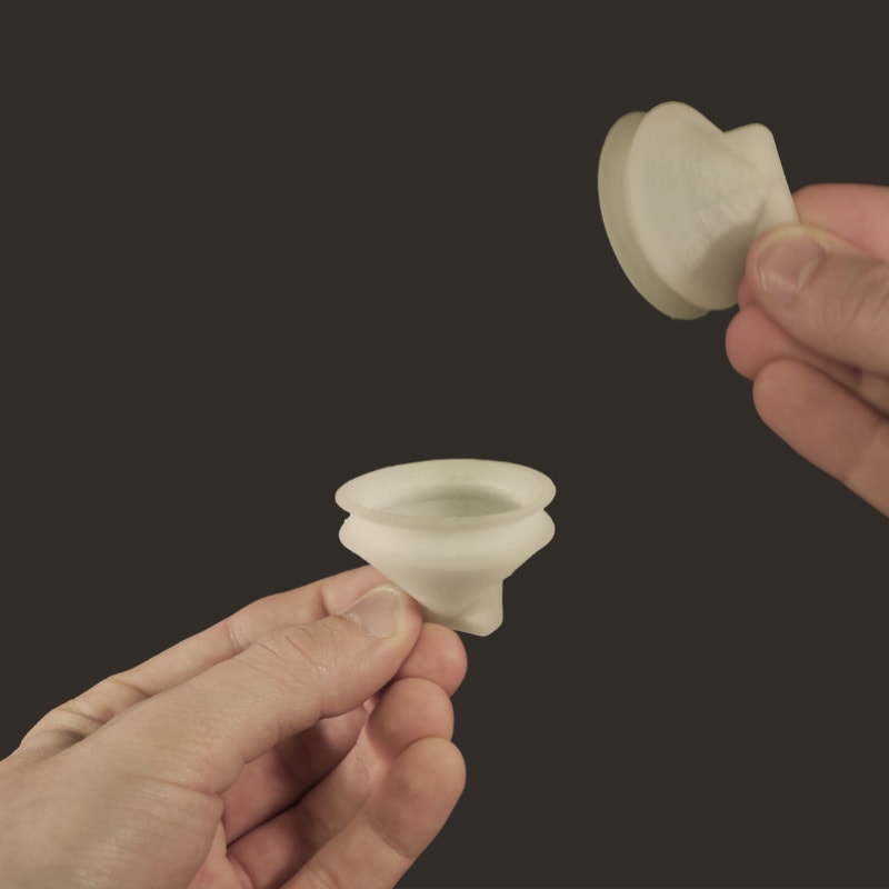
Suction cup and gripping fingers
With the increase of robots in manufacture and assembly lines, the production of grippers is on the rise. Production lines need to be as flexible as possible and changes, e.g. for maintenance, must be performed as quickly as possible.
In this case the goal is to completely eliminate assembly operations and to ensure quick changes of gripping fingers during maintenance.
The gripper should be produced in a flexible material to enable the gripping mechanism and should withstand a sufficient amount of gripping operations.
- Long lead times: Designing a new gripping finger for a specific application takes time and requires sourcing of several components.
- Complex manufacturing: Gripping fingers are usually designed of several components that need to be kept on stock and assembled.
- Machine downtime: Every hour of stillstand in a production line is costly. The gripping finger must therefore be available with short leadtimes and changeover times must be kept short.
While grippers can be produced with a range of AM technologies we present 2 different grippers produced with a ME printer by the French company POLLEN AM.
T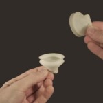 he first design is a suction cup that is produced in one component in a very low hardness TPE. The material used is airtight and can be manufactured in one part.
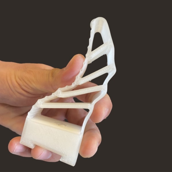
The second part is a gripping finger that has been printed in two materials – ABS for toughness and TPU 33 Shore D to ensure flexibility.
Both parts were printed in an extrusion printer from pellets that are typically used for injection molding.
- Flexibility: The operator of the production line can produce the parts directly on site and is independent of suppliers.
- Less spare parts: Short lead times and the possibility to produce parts in one go reduce the need to keep parts on stock.
- Low production cost: No need for tooling and the possibility to use Pellets lead to low production cost.
- Technology supplier: POLLEN AM
- Technology: Material Extrusion (ME)
- Printer: PAM SERIES P
- Materials: TPE, ABS & TPU
View a video of the application
Suction Cup
You are currently viewing a placeholder content from YouTube. To access the actual content, click the button below. Please note that doing so will share data with third-party providers.
More InformationMulti-material Gripper
You are currently viewing a placeholder content from YouTube. To access the actual content, click the button below. Please note that doing so will share data with third-party providers.
More InformationEnd-use parts
Hydraulic component for Airbus A380
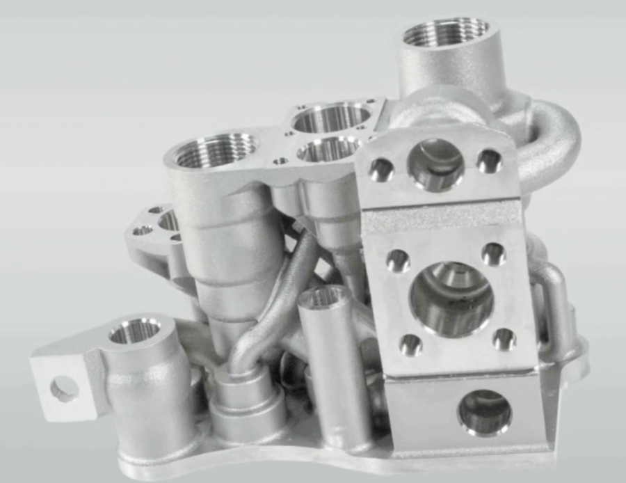
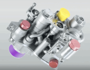
Weight reduction is one of the main drivers for the use of Additive Manufacturing within aviation. The hydraulic manifold, which was produced by LIEBHERR AEROSPACE for an AIRBUS A380 is a great example for this.
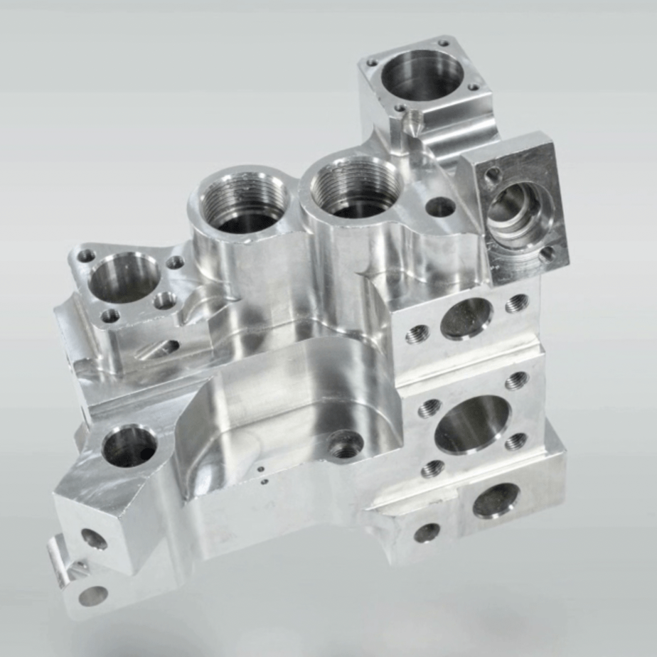
The objective was to replace a conventionally manufactured high-pressure hydraulic valve block with an additively manufactured one. The component is produced by LIEBHERR AEROSPACE.
The primary flight control component moves the spoiler of an AIRBUS A380 aircraft to the desired position during take-off and landing and must thus meet highest quality standards.
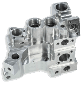 The original component is machined from a forged block with several drillings and assembly operations. This leads to limited design freedom and long lead times.
- Weight: The potential to reduce the weight of the existing component is limited by the complex manufacturing process.
- Qualification: The part needs to meet highest quality standards due to the critical function.
- Assembly: The original part consisted of several components and a complex system of pipes. The design was sub-optimal given limited installation space.
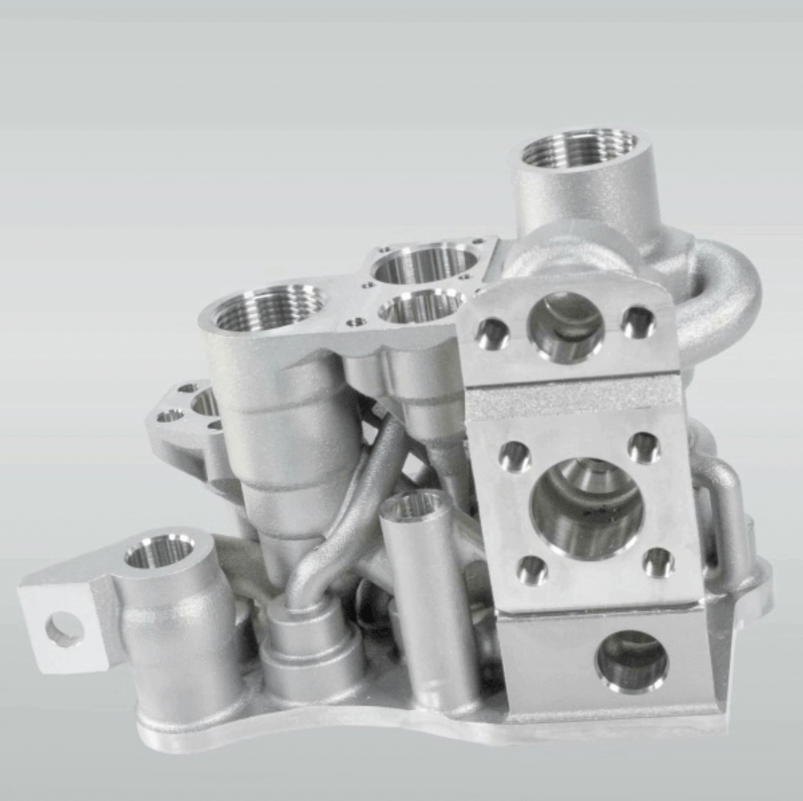
The design was optimized based on the installation space and the goal to keep short connections to interfaces. Material was then only added where necessary, resulting in 35% less weight.
The part was produced on an EOS M290 in titanium. After printing, a heat treatment as well as a treatment of the internal channels was performed.
- 35% weight reduction: The new part is 35% lighter, leading to reduced fuel consumption and CO2 emissions.
- 10 parts eliminated: The new design integrated 10 functional elements into the new valve block, eliminating the complex piping system.
- 75% less production time: The new design eliminates several manufacturing steps, the part can be printed within 1 day.
The printed part fulfilled all certification requirements and has been successfully used on a test flight of the AIRBUS A380 aircraft.
- End user & product: AIRBUS A380
- Machine supplier: EOS
- Part manufacturer: LIEBHERR AEROSPACE
A couple of years from now, we believe that metal 3D-printed parts such as the valve block will be manufactured in series at Lieberr- Aerospace and delivered to our customers.
Alexander Altmann | Lead Engineer Additive Manufacturing, Research & Technology | LIEBHERR AEROSPACE LINDENBERG
Further information on the case study can be found here.
Spare Parts
Spare parts on demand
EVOBUS, a subsidiary of the DAIMLER GROUP, sees increasing challenges in the field of spare parts for their buses. The company’s increasing product portfolio results in over 320,000 spare parts and thus high costs for warehousing and logistics as well as long lead times. In addition, minimum purchase volumes lead to overproduction and often to obsolete parts.
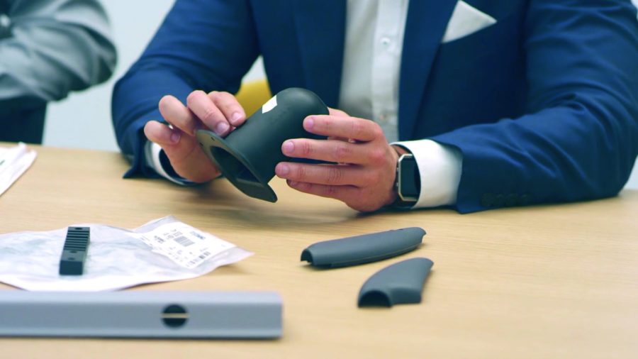
The biggest initial potential for Additive Manufacturing has been identified within polymer components in the interior of the buses.
- Minimum order quantities: minium order quantities of up to 100 parts leads to high warehousing effort and obsolete parts.
- High warehousing costs: A growing product portfolio has led to over 320 000 parts that need to be kept on stock
- Limited service life: Spare parts are promised to the customer for over 15 years after the production has discontinued. After that it is hard to obtain spare parts.
- Sustainability: Shipping parts around the world and scrapping obsolete parts needs to negative environmental footprint.
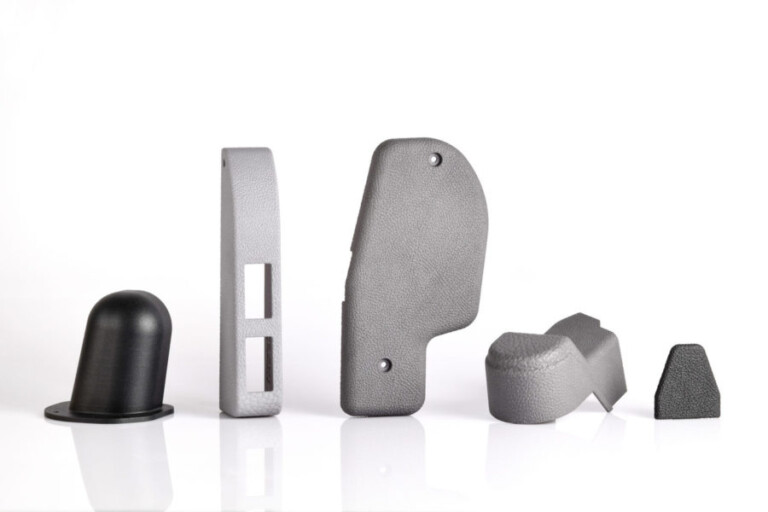
Several spare parts such as covers and armrests from the interior of the bus have been identified as suitable components for Additive Manufacturing. To imitate the surface of the conventionally produced parts, a textured surface was applied during the printing process. After printing, the parts have been colored in a dyeing process and blasted to create a smoother surface.
Selected parts have been produced in Polyamide 12. The majority of components, however, requires a specific flame-resistant material that has to be authorized for the usage in buses.
- No minimum order quantities: Parts can be produced “on demand” in the required quantities, resulting in less obsolete parts
- Reduced need for warehousing: Shorter leadtimes lead to less parts that are kept on stock.
- Shorter lead times: Parts can be produced within days without tooling involved.
- Sustainability: Less obsolete parts leads to a positive environmental impact. Potentially, parts can be produced close to the customer to avoid shipping.
- Machine: EOS FORMIGA P110
- Material: POLYAMIDE 2200
By implementing 3D printing within our CSP business model, we hope to reduce the rising warehousing and tool costs caused by our growing inventory of omnibus spare parts, while also continuing to improve supply performance to our end customers
Ralf Anderhofstadt, Head of Center of Competence 3D-Printing, DAIMLER BUSES
View a video of the project
You are currently viewing a placeholder content from YouTube. To access the actual content, click the button below. Please note that doing so will share data with third-party providers.
More InformationFurther information on the case study can be found here.
Repair
Repair of a seal in a gas turbine
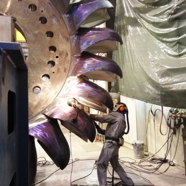
Directed Energy Deposition (DED) technologies, such as Laser Metal Deposition (LMD), are already a mature technology in several industries. Expensive components with high production costs can easily be repaired, meaning that the part or tool is back in use in a short time.
This way, companies not only save time due to long delivery times, but also cost. This is due to the fact that it is usually more cost effective to repair a component than to buy a new one when it comes to expensive materials such as nickel-based alloys. Design changes can also be made on the component.
DED thus allows end users to reduce repair time, save costs and improve the carbon footprint by repairing worn out components instead of producing a new part.
Expensive components, such as compressor seals for gas turbines, are costly to produce and usually come with long lead times. These long lead times are especially costly when a product can not be used during a downtime.
The part on the right is a seal in a gas turbine produced in Inconel 718. Already very low amounts of wear on the edges results in scrap of the entire part.
- Long lead times: Repairing worn out components often takes several months, especially for old equipment that is not in production anymore.
- Sustainability: Throwing away parts and producing new ones comes along with negative consequences for the environment.
- Cost: Cost for repair or replacement are high, and costs resulting from equipment standing still leads to even higher costs.
DED technologies such as Laser Metal Deposition (LMD) can be used to repair worn out components.
The part has been repaired using the LENS technology by OPTOMEC. The repair deposit caused a minor shrinkage of the inside diameters that were subsequently machined to print tolerances. The repaired tool was accepted by the customer. In this example, the cost for the repair was about 45% compared to replacement with a new part.
- High quality repairs:DED enables the repair of existing parts meeting the quality requirements for loaded applications.
- Re-use of expensive parts: Re-using expensive parts instead of throwing them away leads to overall reduced costs.
- Easy to integrate: Integrating DED into the existing workflow brings the potential to reduce the repair time and thus also lowers downtimes.

