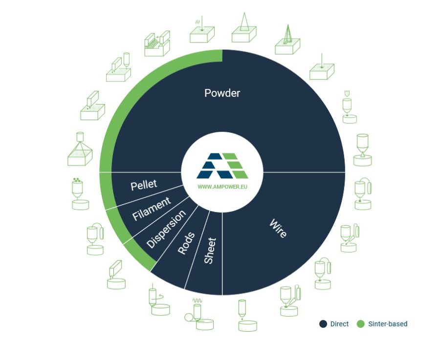
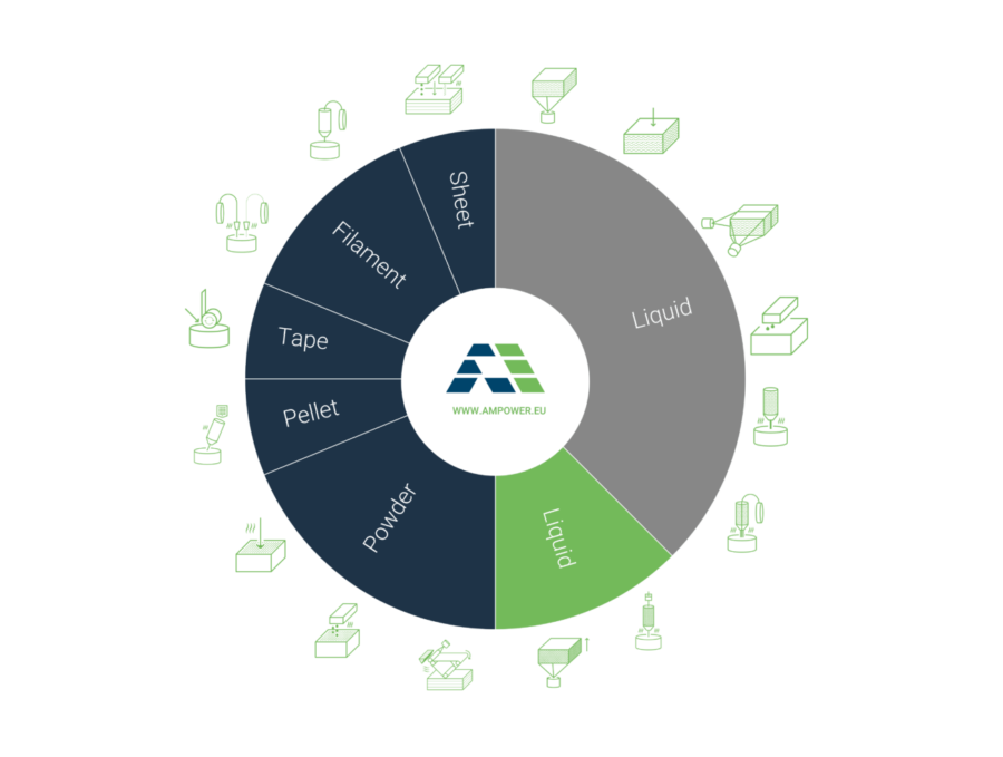
AM Process Overview
Process description:
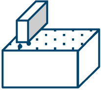
A liquid bonding agent is selectively deposited to join powder materials.
Materials:
Metal and sand
Typical applications:
- Serial metal parts ≈500-20.000
- Printing of sand molds
AM process variants – a selected overview
- Binder Jetting (BJT)
- Multi Jet Fusion© (MJF)

Process description:
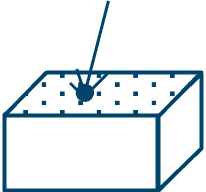
A focused energy source used to fuse materials as they are being deposited.
Materials:
Metal
Typical applications:
- Repair/coating of shafts for oil & gas/heavy duty machinery
- Aviation Ti parts
AM process variants – a selected overview
- Laser Engineering Net Shape (LENS)
- Electron Beam Additive Manufacturing (EBAM)
- Rapid Plasma Deposition

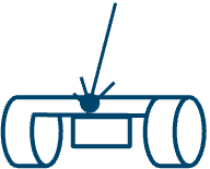
Process description:
Material is selectively dispensed through a nozzle or orifice.
Materials:
Metal, polymer and composite
Typical applications:
- 3D printing @ home
- High performance polymers (e.g. PEEK)
AM process variants – a selected overview
- Fused Deposition Modeling (FDM) – Polymer
- Arburg Plastic Freeforming (APF) – Polymer

Process description:
Droplets of build material are selectively deposited.
Materials:
Metal, polymer and wax
Typical applications:
- Multicolor/-mate-rial prototypes
- Wax patterns for jewelry
- Molds for investmment casting
AM process variants – a selected overview
- Material Jetting (MJ) – Polymer
- Multi-Jet Modeling (MJM) (also: MultiJet Printing (MJP), PolyJet) – Polymer
- NanoParticle Jetting (NPJ) – Polymer
Process description:
Energy source selectively fuses regions of a powder bed.
Materials:
Metal and polymer
Typical applications:
- Polyamer prototypes
- Complex metal parts: Implants, fuel nozzle, turbine blades
AM process variants – a selected overview
- Laser-beam PBF of polymers (L-PBF) (also: Selective Laser Sintering (SLS)) – Polymer
- LB-PBF of metals (L-PBF) (also: Direct Metal Laser Sintering (DMLS), Selective Laser Melting (SLM), Laser Metal Fusion (LMF)) – Metal
- Electron beam PBF of metals (E-PBF) (also: Electron Beam Melting (EBM)) – Metal
Process description:
Sheets of material are bonded to form a part.
Materials:
Composite, paper
Typical applications:
Full color paper prototypes
AM process variants – a selected overview
- Laminated Object Manufacturing
(LOM) – Other
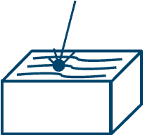
Process description:
Liquid photopolymer in a vat is selectively cured by light-activated polymerization.
Materials:
Ceramic, photopolymer
Typical applications:
- Silicone hearing aids
- High surface finish prototypes
AM process variants – a selected overview
- Stereolithography (SLA) – Polymer
- Digital Light Processing (DLP) – Polymer
- Continuous Digital Light Processing (CLIP) – Polymer
- Lithography-based Ceramic – Ceramic Manufacturing (LCM) – Ceramic
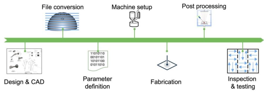

Computer Aided Design
Every AM process starts with 3D CAD information of the part to be produced.
Read MoreStep 1
File Conversion
Once the CAD file has been finalized, it must be converted - usually into an STL file.
Read MoreStep 2
Parameter Definition
Before starting the print job, machine-specific parameters need to be assigned.
Read MoreStep 3

Machine Setup
Once the print file has been sent to the printer, the machine needs to be set up physically.
Read MoreStep 4

Post Processing
Post processing refers to the often manual operations that are required after a print to finish a part for its application purpose.
Read MoreStep 6
Quality Control & Testing
The final step is the quality control and testing of a part.
Read MoreStep 7
By loading the video, you agree to YouTube's privacy policy.
Learn more
By loading the video, you agree to YouTube's privacy policy.
Learn more
By loading the video, you agree to YouTube's privacy policy.
Learn more
Source: hubs
By loading the video, you agree to YouTube's privacy policy.
Learn more
By loading the video, you agree to YouTube's privacy policy.
Learn more
Source: hubs
By loading the video, you agree to YouTube's privacy policy.
Learn more
Source: Thomáš Vít
By loading the video, you agree to YouTube's privacy policy.
Learn more


