Software Tools for Part Identification

Software tools for Part Identification

Software support for the screening of your parts

When trying to identify the right parts for Additive Manufacturing it is easy to get lost in the details. Digital tools highlighted in this section are thus great to support in this process. We still want to highlight the importance of understanding the basics of the technology and the methodology to validate what is suggested by software. Also, while software is great in suggesting the best technology or providing a quick cost estimate, the additional value AM can add to a certain application still needs to be identified “manually” by the end user. 

In this section, we want to give an overview of software tools developed by CASTOR, 3YOURMIND and 3D SPARK.

Image source: 3YOURMIND

What you will find in this section

CASTOR

CASTOR software overview

CASTOR was founded in 2017 by David Calderon and Omar Elad in Tel Aviv. Since then, their software for automated screening has been continuously developed and is today used by companies such as DANFOSS, STANLEY BLACK & DECKER and EVONIK.

How it works

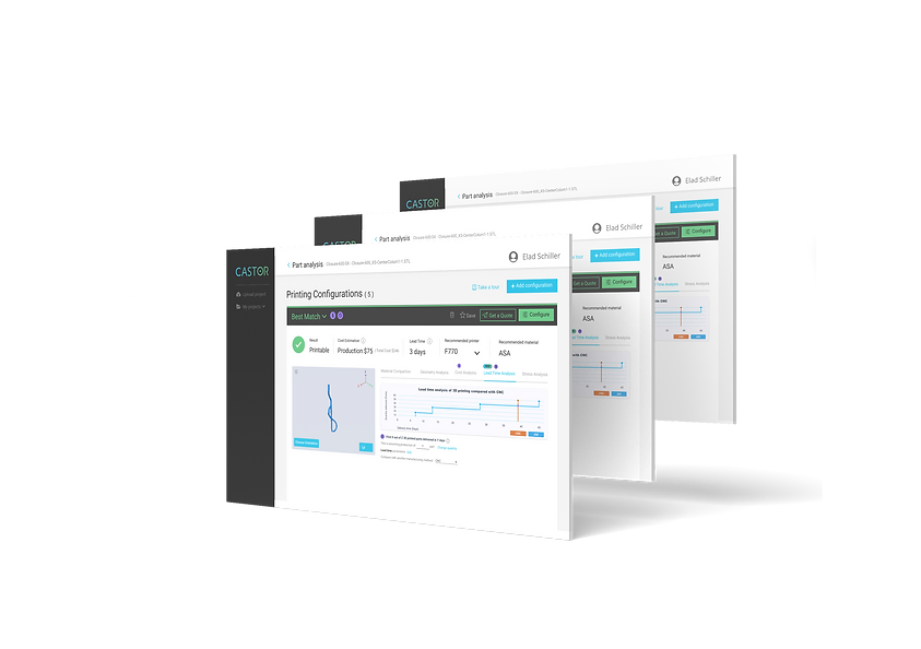
Users can either upload an entire bill of materials directly from the PLM system to screen a huge number of parts or upload individual CAD assembly files. The software then performs an automatic analysis within a few seconds including the best matching technology, material and a cost estimate.

During this process, an algorithm suggests design adjustments, such as possibilities for weight reduction or part consolidation

Image source: CASTOR

Video

An overview of CASTOR and its functionality can be found in the following video.

YouTube

By loading the video, you agree to YouTube's privacy policy.
Learn more

Load video

3YOURMIND

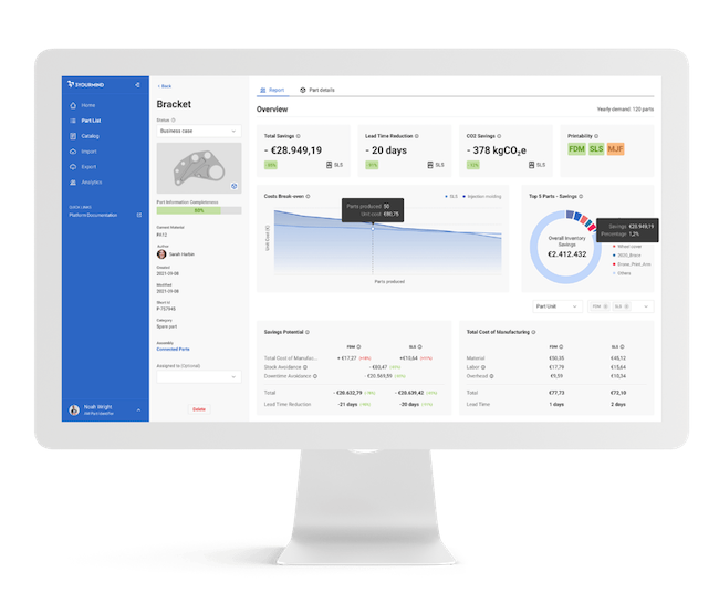
3YOURMIND software overview

3YOURMIND was founded in 2014 in Berlin and is thus the most mature solution that is presented in this section. Since then the company grew to over 65 employees and has project management offices in Paris, Munich, Novi and San Francisco. 

Their customer base includes large enterprises such as VOLKSWAGEN, DEUTSCHE BAHN and CONTINENTAL but also AM companies such as ERPRO or PROTOTEC.

How it works

3YOURMIND offers different approaches including an inventory analysis, which is an automated analysis of the ERP and PLM data, and a use case screening, which is a user-led approach where employees, customers or vendors can enter part information that are then analyzed and can then be assessed by an AM expert.

In the use case screening, users enter key part information such as component size, material and quantity and can upload a 3D file. This data is then analyzed by an algorithm that can be customized based on each company. The user gets initial feedback on the technical and economic suitability of the component and the AM expert within a company can view all screened parts, request more details or define next steps.

What stands out for 3YOURMIND is their broad range of software offering. Besides part identification, which is part of their Agile PLM module, the company offers an Agile ERP and Agile MES solution. This way, 3YOURMIND can cover the entire process from part identification through customer and order management to scheduling and tracking of internal or external part production.

Image source: 3YOURMIND

Video

An overview of 3YOURMIND and the use case screening can be found in the following video.

YouTube

By loading the video, you agree to YouTube's privacy policy.
Learn more

Load video

3D SPARK

3D SPARK software overview

3D SPARK is a Hamburg-based company that was founded in 2021 by Ruben Meuth, Dr.-Ing. Fritz Lange and Dr.-Ing. Arnd Struve that all previously worked at the German Fraunhofer Institute IAPT. 

Within a short time 3D SPARK has launched their software to the market and has attracted customers like ALSTOM, ZF and METSHAPE.

How it works

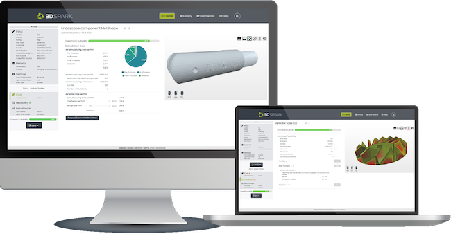
Users can upload CAD files, drawing or other documents which are automatically analyzed. The user can then add additional information such as AM material, quantity, make/buy, printing location etc. 

Their algorithm then compares different printing orientations for the part regarding cost, quality and lead time and suggests the optimum. For this orientation, a cost analysis breaks down production costs based on a visualized process-chain proposal, to which additional process steps (painting, shipment, etc.) can be added to fine tune the costing. Additionally, the feasibility analysis identifies critical part features, and the break-even analysis suggests the most cost-efficient production method for a certain quantity.

What stands out about 3D SPARK is the precision of their printability check and cost calculation for 11 AM processes. This is based on their orientation optimization algorithm that within seconds analyzes a wide range of different orientations and then selects the optimum, repeatedly saving more than 75% printing costs.

Image source: 3D Spark

Video

An overview of the 3D SPARK software can be found in the following video.

YouTube

By loading the video, you agree to YouTube's privacy policy.
Learn more

Load video

Free Trial of the 3D SPARK platform

3D SPARK currently offers a free trial to all users of the AMPOWER Academy. To try out their platform, simply register via the following link: 

Register to the 3D SPARK Platform

Other companies

Part Identification Software: A Growing Landscape

In addition to the companies highlighted on this page, several others are advancing part identification software for Additive Manufacturing (AM). These include Cognitive Design Systems (CDS) from France, Select AM from Finland, Spare Parts 3D from France, and DIMANEX from the Netherlands. While the functionalities of their tools vary, all provide solutions to evaluate the suitability of parts for AM.

Recently, many of these platforms have also incorporated carbon footprint calculations into their analysis, reflecting the industry’s increasing focus on sustainability.

Sinter-based AM technologies and process chain

Sinter-based AM - a technology overview

Many different printing technologies - one sintering process

The sinter-based AM (SBAM) technologies have, as the name suggests, the sintering process in common. In this process, the printed green part is consolidated into a dense part and receives its final properties. The green part can be printed in advance using different technologies.They all have in common that metal powder is bound to the desired shape by a binder. The best-known printing technologies include Binder Jetting and Filament Material Extrusion.

In this section, you learn everything about the sinter-based AM  process chain and get an overview of the different printing technologies.

Goal and structure of this course

This course is aimed at engineers, designers and other professionals that are working closely with sinter-based AM technologies. The goal is to cover the most important aspects that will enable engineers and designers to fully grasp the capabilities and technical limitations of the printing technologies and the sintering process to succeed in technology selection and part design. Besides going through the course from the beginning until the end, this course can also act as a constant source of knowledge while working on AM projects. 

The course is structured into the following sections.

This section will start with an overview of the sinter-based AM process chain and its printing technologies, followed by a technology deep dive into the most important aspects of the BJT technology, followed by a closer look at the debinding and sintering step also including sintering simulation .

The second section will provide an overview of the different materials that are available as well as part characteristics that can be achieved with the BJT process and typical methods for quality assurance. Finally, several common defects in the BJT process are presented. 

The last section will act as a guideline for designers. Besides generally describing the process when designing for Additive Manufacturing, actionable restrictions and guidelines for the BJT process are provided. The final section will present several design examples from different industries. 

What you will find in this section

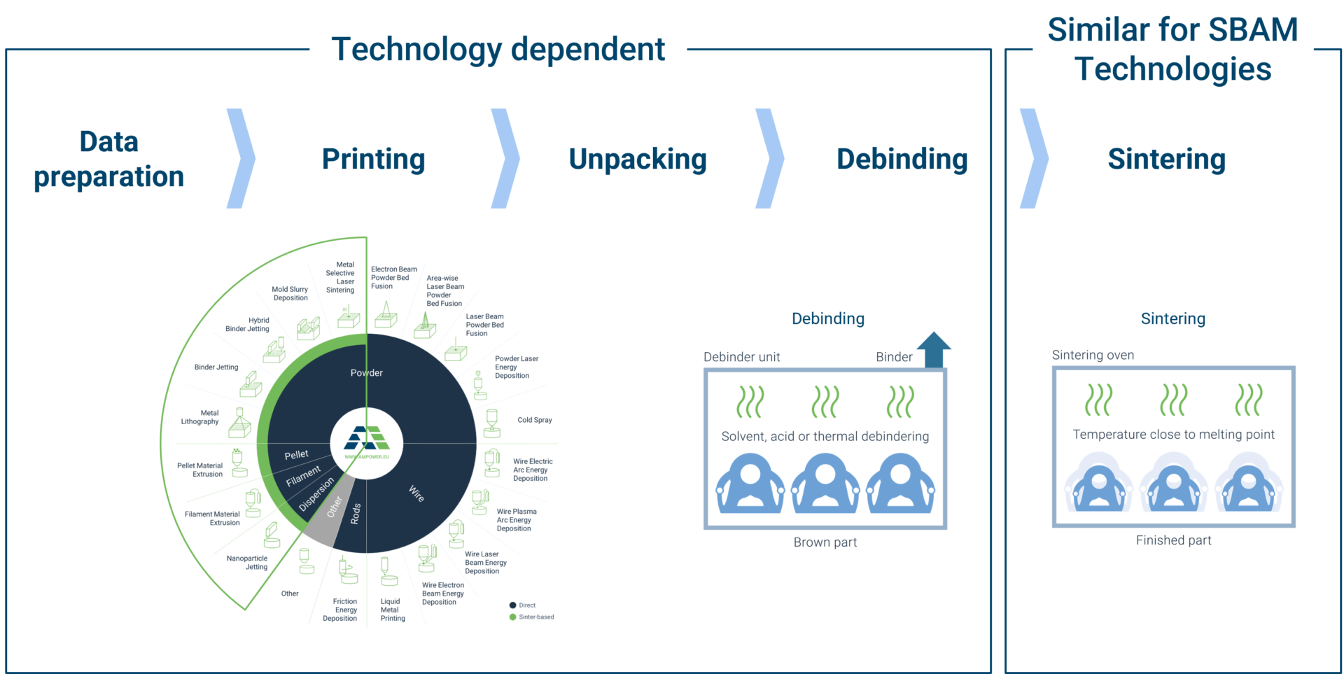
Sinter-based AM process chain

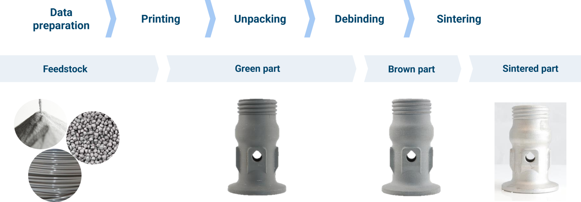
From digital model to finished part

Data preparation

Simulation to compensate the deformation during the sintering step, nesting of parts and definition of printing parameters

Printing

Through various printing processes, different feedstocks such as metal powders, filaments, pellets or dispersions are processed into green parts

Unpacking

Unpacking of fragile green parts needs to be done carefully and is typically a manual process.

Debinding

Debinding describes the process of removing the binder which results in a brown part

Sintering

To reach the structural integrity of a metal part, a sinter process is required. The powder particles fuse together to a coherent, solid structure via a mass transport that occurs at the atomic scale driven via diffusional forces.

The brown part shrinks ~13-21 % in each direction.

The process chain of sinter-based technologies differs from other AM Technologies. Especially the post-printing processes (debinding and sintering) are crucial to achieve the intended mechanical properties.

Technology principle

How does Binder Jetting work?

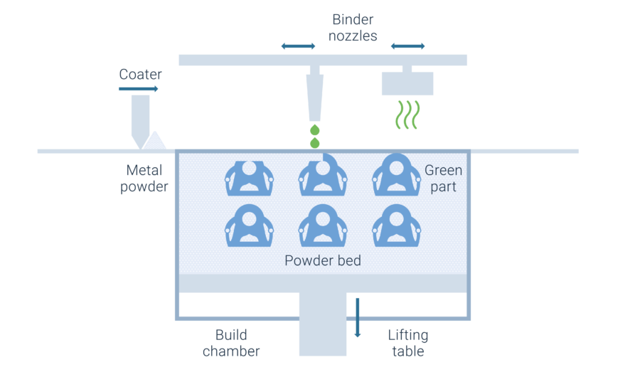
Binder Jetting is a powder based Additive Manufacturing technology in which a liquid polymer binder is selectively deposited onto the powder bed binding the metal particles and forming a green body.

The metal powder is applied to a build platform in a typical layer thickness of 40 µm to 100 µm. Subsequently a modified 2D print head apply a binder selectively onto the powder bed. Depending on machine technology a hardening or curing process of the binder is performed in parallel for each layer and/or at the end of the whole build. During the in-situ curing process a heat source is used to solidify the binder and form a solid polymer – metal powder composite.

Working Principle of Binder Jetting

Afterwards the build platform moves downward by the amount of one layer thickness and a new layer of powder is applied. Again, the liquid binder is deposited and hardened in the required regions of the next layer to form the green body. This process is repeated until the complete part is printed. After the complete printing process is finished the parts have to be removed from the “powder cake” meaning the surrounding loose but densified powder. To improve the removal of the excess powder from the green body often brushes or a blasting gun with air pressure are used.

To create a dense metal part the 3D printed green body has to be post-processed in a debinding and sintering process. Similar to the metal injection molding process BJT parts are placed in a high temperature furnace, where the binder is burnt out and the remaining metal particles are sintered together. The sintering results in densification of the 3D printed green body to a metal part with high densities of 97 % to 99,5%, dependent of the material.

Printing Technologies

Metal Binder Jetting

Binder Jetting is a powder based Additive Manufacturing technology in which a liquid polymer binder is selectively deposited onto the powder bed binding the metal particles and forming a green body.

The metal powder is applied to a build platform in a typical layer thickness of 40 µm to 100 µm. Subsequently a modified 2D print head apply a binder selectively onto the powder bed. Depending on machine technology a hardening or curing process of the binder is performed in parallel for each layer and/or at the end of the whole build. During the in-situ curing process a heat source is used to solidify the binder and form a solid polymer – metal powder composite.

Working Principle of Binder Jetting

Material Extrusion

Binder Jetting is a powder based Additive Manufacturing technology in which a liquid polymer binder is selectively deposited onto the powder bed binding the metal particles and forming a green body.

The metal powder is applied to a build platform in a typical layer thickness of 40 µm to 100 µm. Subsequently a modified 2D print head apply a binder selectively onto the powder bed. Depending on machine technology a hardening or curing process of the binder is performed in parallel for each layer and/or at the end of the whole build. During the in-situ curing process a heat source is used to solidify the binder and form a solid polymer – metal powder composite.

Working Principle of Binder Jetting

Mold Slurry Deposition

Binder Jetting is a powder based Additive Manufacturing technology in which a liquid polymer binder is selectively deposited onto the powder bed binding the metal particles and forming a green body.

The metal powder is applied to a build platform in a typical layer thickness of 40 µm to 100 µm. Subsequently a modified 2D print head apply a binder selectively onto the powder bed. Depending on machine technology a hardening or curing process of the binder is performed in parallel for each layer and/or at the end of the whole build. During the in-situ curing process a heat source is used to solidify the binder and form a solid polymer – metal powder composite.

Working Principle of Binder Jetting

Metal Selective Laser Sintering

Binder Jetting is a powder based Additive Manufacturing technology in which a liquid polymer binder is selectively deposited onto the powder bed binding the metal particles and forming a green body.

The metal powder is applied to a build platform in a typical layer thickness of 40 µm to 100 µm. Subsequently a modified 2D print head apply a binder selectively onto the powder bed. Depending on machine technology a hardening or curing process of the binder is performed in parallel for each layer and/or at the end of the whole build. During the in-situ curing process a heat source is used to solidify the binder and form a solid polymer – metal powder composite.

Working Principle of Binder Jetting