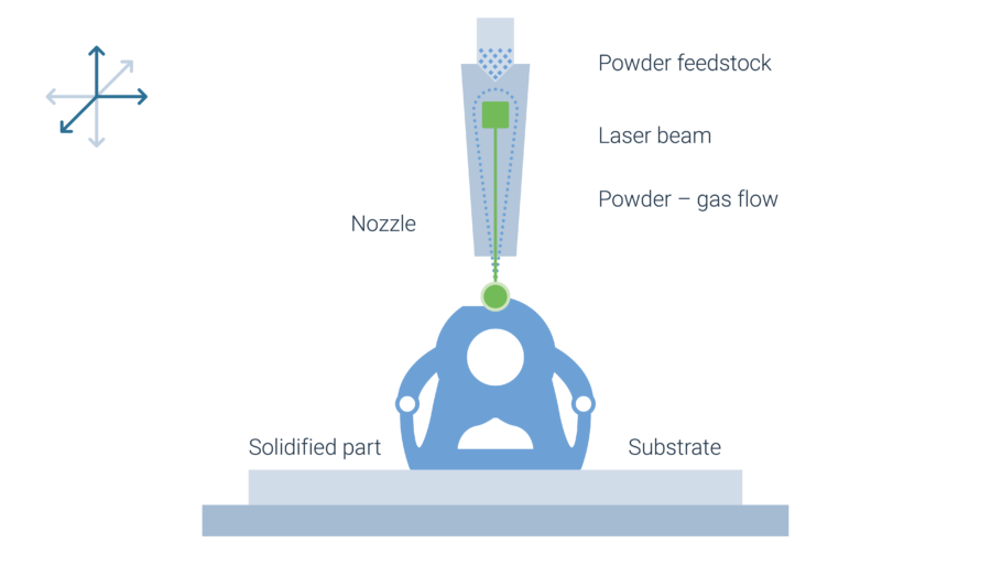
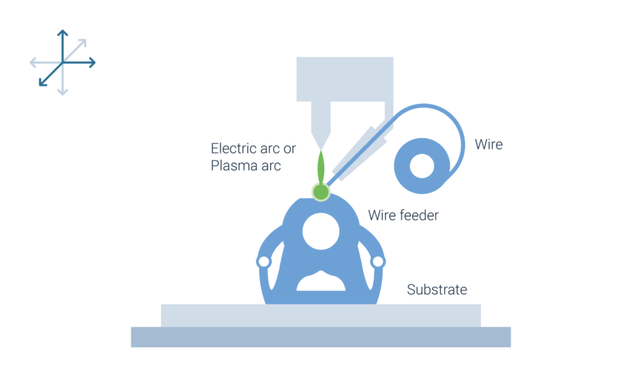
Directed Energy Deposition (DED)


By loading the video, you agree to YouTube's privacy policy.
Learn more

By loading the video, you agree to YouTube's privacy policy.
Learn more


