In-process quality assurance (QA) systems play a critical role in ensuring the quality and consistency of parts produced using L-PBF technology. These systems involve a set of procedures and protocols that are applied during the manufacturing process to ensure that the final product meets the required specifications and quality standards. Some of the failure types that in-process QA systems can identify are delamination, overheating, uneven powder distribution or wrong machine set-up.
The analysis and interpretation of the QA data is often still a manual process requiring deep expertise. More and more intelligent software is coming up, however, that promise to automate the QA process and potentially even perform corrective actions.
On a global level, sensors are used to monitor the overall state of the L-PBF process. This includes the O2 content and pressure in the atmosphere and the laser current.
Compared to other monitoring systems, they have a low sampling rate and low resolution and thus lead to relatively small data packages.
Powder layer control
Identification of missing powder and part defects
Schematic illustration of the local L-PBF monitoring process
Schematic illustration of the powder layer control monitoring
Powder layer control is an effective way to monitor the recoating during the L-PBF process that has become standard for most machine manufacturers. A picture of the powder bed is taken before and after the application of a new layer of powder and the applied powder is depicted as grey scale picture.
This way it can be analysed if powder is missing on a layer, e.g. because of poor powder quality or false machine settings, or if parts are bending up and are thus defective. Since such a system generates over 1 000 pictures for a typical build job, the analysis must be guided by intelligent software.
Melt pool monitoring
Melt pool control for in-depth quality assurance
Melt pool monitoring provides the most in-depth analysis of the AM process. The systems include high speed CCD cameras that translate the electrical signals into digital values to measure the melt pool dimensions as well as diodes and a pyrometer to measure the melt pool intensity. Due to the high complexity, 2D or 3D mapping of the data is required for making the most out of the systems. The identification and correlation of abnormalities to defects remains extremely difficult, especially when building a part for the first time. Melt pool monitoring systems have a very high sampling rate and resolution and thus lead to very large data packages.
Schematic illustration of the melt pool monitoring process
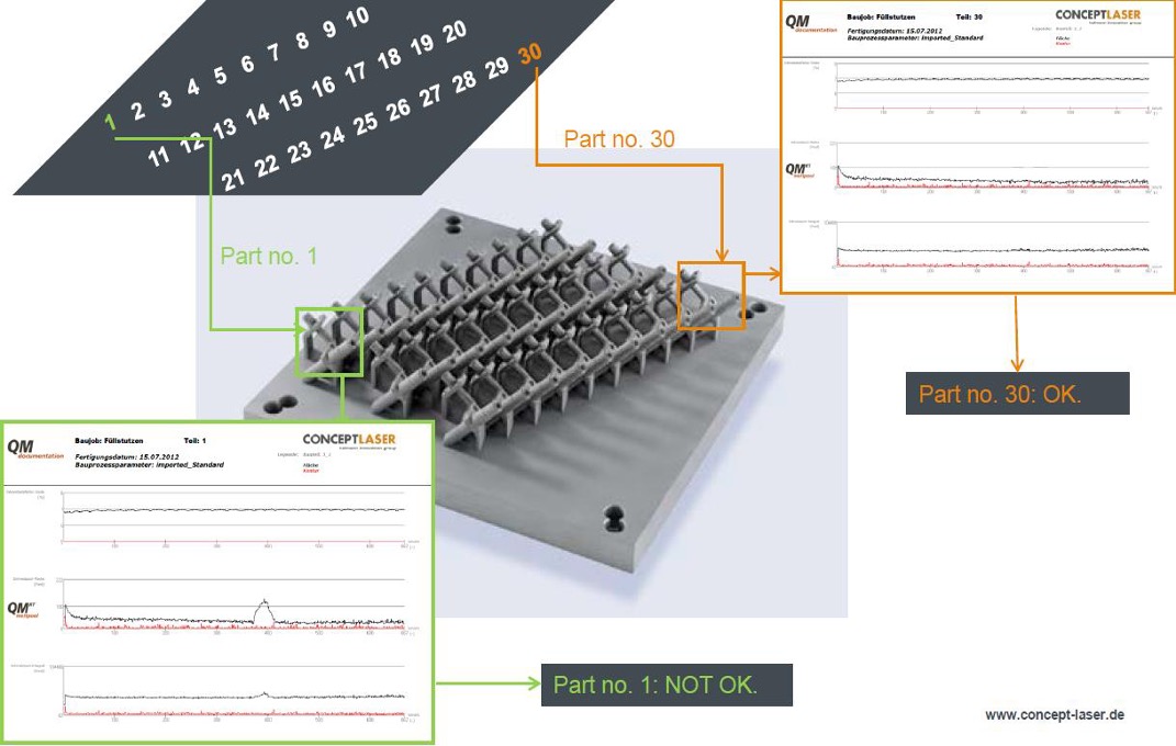
Comparison of sensor data between identical parts on a CONCEPT LASER system
Source: CONCEPT LASER
The picture above shows how melt pool monitoring can be used for quality assurance in the LPBF process. 30 identical parts are produced in the same build job, each using the exact same process parameters. The signals measuring the melt pool dimensions and intensity should thus be identical for all 30 parts. Part 1 shows a deviating signal at a certain point, indicating a process abnormality that could lead to a certain defect. This part should thus be either be directly rejected or analyzed in more detail, e.g. using a CT scan.
Sinter-based AM technologies and process chain
Sinter-based AM - a technology overview
Many different printing technologies - one sintering process
The sinter-based AM (SBAM) technologies have, as the name suggests, the sintering process in common. In this process, the printed green part is consolidated into a dense part and receives its final properties. The green part can be printed in advance using different technologies.They all have in common that metal powder is bound to the desired shape by a binder. The best-known printing technologies include Binder Jetting and Filament Material Extrusion.
In this section, you learn everything about the sinter-based AM process chain and get an overview of the different printing technologies.
Goal and structure of this course
This course is aimed at engineers,designers and other professionals that are working closely with sinter-based AM technologies. The goal is to cover the most important aspects that will enable engineers and designers to fully grasp the capabilities and technical limitations of the printing technologies and the sintering process to succeed in technology selection and part design. Besides going through the course from the beginning until the end, this course can also act as a constant source of knowledge while working on AM projects.
The course is structured into the following sections.
This section will start with an overview of the sinter-based AM process chain and its printing technologies, followed by a technology deep dive into the most important aspects of the BJT technology, followed by a closer look at the debinding and sintering step also including sintering simulation .
The second section will provide an overview of the different materials that are available as well as part characteristics that can be achieved with the BJT process and typical methods for quality assurance. Finally, several common defects in the BJT process are presented.
The last section will act as a guideline for designers. Besides generally describing the process when designing for Additive Manufacturing, actionable restrictions and guidelines for the BJT process are provided. The final section will present several design examples from different industries.
Simulation to compensate the deformation during the sintering step, nesting of parts and definition of printing parameters
Printing
Through various printing processes, different feedstocks such as metal powders, filaments, pellets or dispersions are processed into green parts
Unpacking
Unpacking of fragile green parts needs to be done carefully and is typically a manual process.
Debinding
Debinding describes the process of removing the binder which results in a brown part
Sintering
To reach the structural integrity of a metal part, a sinter process is required. The powder particles fuse together to a coherent, solid structure via a mass transport that occurs at the atomic scale driven via diffusional forces.
The brown part shrinks ~13-21 % in each direction.
The process chain of sinter-based technologies differs from other AM Technologies. Especially the post-printing processes (debinding and sintering) are crucial to achieve the intended mechanical properties.
Technology principle
How does Binder Jetting work?
Binder Jetting is a powder based Additive Manufacturing technology in which a liquid polymer binder is selectively deposited onto the powder bed binding the metal particles and forming a green body.
The metal powder is applied to a build platform in a typical layer thickness of 40 µm to 100 µm. Subsequently a modified 2D print head apply a binder selectively onto the powder bed. Depending on machine technology a hardening or curing process of the binder is performed in parallel for each layer and/or at the end of the whole build. During the in-situ curing process a heat source is used to solidify the binder and form a solid polymer – metal powder composite.
Working Principle of Binder Jetting
Afterwards the build platform moves downward by the amount of one layer thickness and a new layer of powder is applied. Again, the liquid binder is deposited and hardened in the required regions of the next layer to form the green body. This process is repeated until the complete part is printed. After the complete printing process is finished the parts have to be removed from the “powder cake” meaning the surrounding loose but densified powder. To improve the removal of the excess powder from the green body often brushes or a blasting gun with air pressure are used.
To create a dense metal part the 3D printed green body has to be post-processed in a debinding and sintering process. Similar to the metal injection molding process BJT parts are placed in a high temperature furnace, where the binder is burnt out and the remaining metal particles are sintered together. The sintering results in densification of the 3D printed green body to a metal part with high densities of 97 % to 99,5%, dependent of the material.
Technology Variation 1
Technology Variation 2
Technology Variation 3
Technology Variation 1
Binder Jetting with single print head
In classic Binder Jetting systems such as the ones distributed by EXONE or DIGITAL METAL the liquid binding agent is selectively deposited with a single print head. Meaning the width of the print head does not cover the full width of the powder bed. Therefore, the print head moves multiple times in xy-direction over the powder bed to completely cover the printing area and distributing the polymer binder.
Technology Variation 2
Binder Jetting with single pass jetting
The SINGLE PASS JETTING technology was developed by DESKTOP METAL and HEWLETT PACKARD. The width of the printing head covers the full width of the powder bed. When the printhead passes over the powder bed, binder is released from more than 30,000 small nozzles and the whole powder layer is selectively immersed in binder in one pass. The process is bi-directional which means that the binder deposition takes place in both moving directions of the printhead. With these modifications the printing speed is significantly increased.
A similarly fast technology is the METAL JET process by HEWLETT PACKARD. In a single pass, a liquid printing agent is applied to the powder layer and subsequently partially evaporated to form the binding polymer around the metal powder. After the completion of the print an additional curing to achieve the full green body stability is needed.
Technology Variation 3
Binder Jetting with full layer jetting
3DEO combines the Binder Jetting process with a subsequent machining process. Different from conventional Binder Jetting processes, the binder is not only deposited selectively but onto the entire powder layer. After hardening of the complete layer, the part geometry is shaped through a milling process every couple of layers by cutting the part contour out of the binder powder composite.
Printing Technologies
Metal Binder Jetting
Binder Jetting is a powder based Additive Manufacturing technology in which a liquid polymer binder is selectively deposited onto the powder bed binding the metal particles and forming a green body.
The metal powder is applied to a build platform in a typical layer thickness of 40 µm to 100 µm. Subsequently a modified 2D print head apply a binder selectively onto the powder bed. Depending on machine technology a hardening or curing process of the binder is performed in parallel for each layer and/or at the end of the whole build. During the in-situ curing process a heat source is used to solidify the binder and form a solid polymer – metal powder composite.
Working Principle of Binder Jetting
Material Extrusion
Binder Jetting is a powder based Additive Manufacturing technology in which a liquid polymer binder is selectively deposited onto the powder bed binding the metal particles and forming a green body.
The metal powder is applied to a build platform in a typical layer thickness of 40 µm to 100 µm. Subsequently a modified 2D print head apply a binder selectively onto the powder bed. Depending on machine technology a hardening or curing process of the binder is performed in parallel for each layer and/or at the end of the whole build. During the in-situ curing process a heat source is used to solidify the binder and form a solid polymer – metal powder composite.
Working Principle of Binder Jetting
Mold Slurry Deposition
Binder Jetting is a powder based Additive Manufacturing technology in which a liquid polymer binder is selectively deposited onto the powder bed binding the metal particles and forming a green body.
The metal powder is applied to a build platform in a typical layer thickness of 40 µm to 100 µm. Subsequently a modified 2D print head apply a binder selectively onto the powder bed. Depending on machine technology a hardening or curing process of the binder is performed in parallel for each layer and/or at the end of the whole build. During the in-situ curing process a heat source is used to solidify the binder and form a solid polymer – metal powder composite.
Working Principle of Binder Jetting
Metal Selective Laser Sintering
Binder Jetting is a powder based Additive Manufacturing technology in which a liquid polymer binder is selectively deposited onto the powder bed binding the metal particles and forming a green body.
The metal powder is applied to a build platform in a typical layer thickness of 40 µm to 100 µm. Subsequently a modified 2D print head apply a binder selectively onto the powder bed. Depending on machine technology a hardening or curing process of the binder is performed in parallel for each layer and/or at the end of the whole build. During the in-situ curing process a heat source is used to solidify the binder and form a solid polymer – metal powder composite.
Working Principle of Binder Jetting
Login
Accessing this course requires a login. Please enter your credentials below!