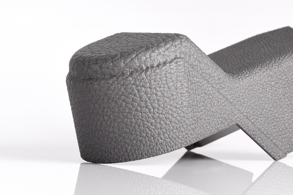
A quick introduction to Additive Manufacturing

What is Additive Manufacturing?

A definition of Additive Manufacturing

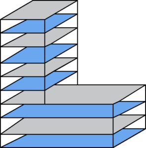
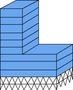
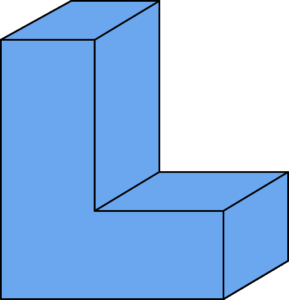
Additive Manufacturing (AM), also known as industrial 3D printing, is the process of creating objects from 3D-model data layer-by-layer, as opposed to subtractive manufacturing methodologies.
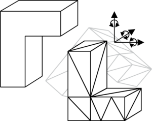
The basic AM principle

Additive Manufacturing includes a wide range of technologies and terminologies. In order to make a clear distinction between AM and other manufacturing technologies, ASTM first published standard F2792 in 2009 with a clear definition, clustering all AM processes into 7 sub-categories. We will give an overview of these categories later in this course. 

Terminologies

Selected terminologies for Additive Manufacturing

Over the years, several terminologies have emerged. While Rapid Prototyping (RP) has been most commonly used in the early days, Additive Manufacturing has become the standard terminology in an industrial context today. Other terms such as industrial 3D printing, are often used interchangeably and can be found on the right. Besides these general terminologies, several companies have coined proprietary terminologies for their processes such as Multi Jet Fusion by HP or the MoldJet Technology by Tritone. 
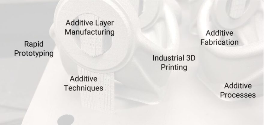
Common Terminologies for Additive Manufacturing

Benefits

AM with benefits for complex parts with low production volume

Additive Manufacturing is often seen as the “holy grail”, some people going as far that it will completely replace conventional manufacturing technologies. We usually describe AM as another tool in the toolbox that brings several benefits, but also a variety of challenges.

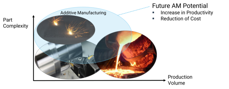
Additive Manufacturing vs Conventional Manufacturing

As of today, Additive Manufacturing is generally addressing a niche where conventional manufacturing lacks competitiveness. This often covers applications with a  low production volume and high complexity. Future developments will continuously increase the productivity and thus reduce the costs. This will lead to a bigger overlap between the technologies and thus more applications where AM is competitive.
 

Cost vs. batch size
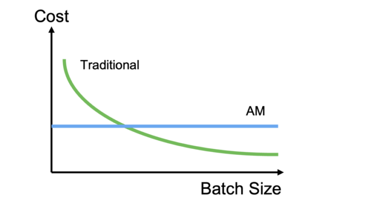
cost vs. batch size

Since Additive Manufacturing is a digital process where no individual tools are required and the CAD model acts as production data, it often has cost benefits compared to traditional technologies for small batch sizes. In a simplified way, there are no economies of scale, meaning that costs do not decrease with the batch size. Therefore, Additive Manufacturing is specifically suitable for low batch sizes.

Cost vs. complexity
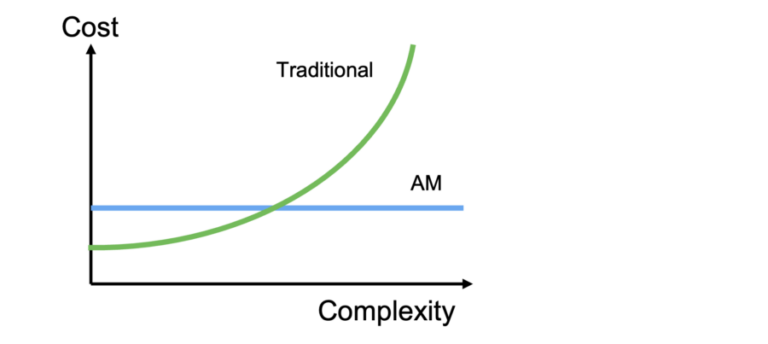
cost vs. complexity

Complexity is no cost driver for Additive Manufacturing opposed to most traditional technologies. The cost driver for most Additive Manufacturing technologies is the part volume, meaning it can even reduce the production cost when creating more lightweight, complex shapes in a smart way. 

We have summarised the most important advantages of AM compared to conventional manufacturing technologies below. For each advantage, you can find one application example. Further examples can be found in the courses on Metal and Polymer Technologies. 

AM offers the potential to significantly reduce the time to market. The ability to quickly iterate different designs and the fact that the CAD model directly acts as production data speeds up the development process. 

At the same time, there is no need to produce toolings, which can reduce the development time for new products from several months to weeks. 

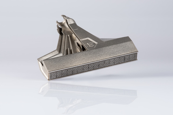
Application example for faster product development and time to market: Spoiler closeout seals


AM has the potential to reduce the number of process steps and thus leads to lower manufacturing complexity. Especially complex parts usually require a combination of several technologies and processing steps. Here AM offers the potential to produce semifinished parts in one go.

It is important, however, to take the number of post processing operations that will be required into account. 

Application example for simplified manufacturing processes: 1/2 scale liner

AM offers the potential to produce parts in low quantities at relatively low cost. This comes from the fact that no tooling is required.

Generally speaking, AM is therefore especially competitive for low- to mid production volumes. We will discuss the suitability of different technologies for mid- to high volumes in the technology section of this course. 

Application example for cost-efficient production of small batch sizes: Coupling hub


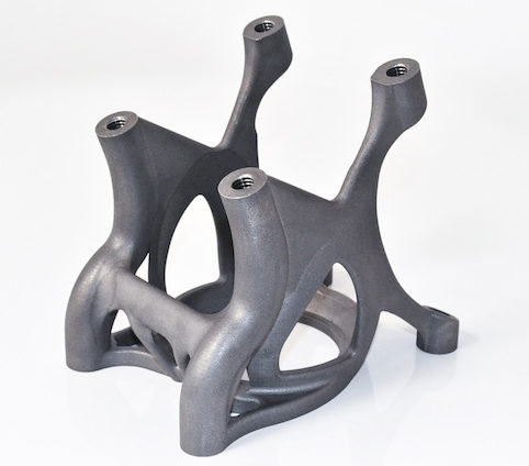
AM gives designers increased freedom of design when compared to conventional technologies such as casting or milling. The lack of design constraints requires that designers are familiar with design for AM guidelines and parts usually need to be redesigned according to the function of the part. 

Popular examples include internal channels, thin walls and bionic designs.

Application example for increased design freedom: customized car panel

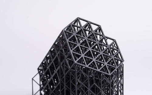
One common application of AM is to create lightweight designs. This can for example be achieved using design features such as lattice structures and by only adding material where it is needed. 

Lightweight parts often come along with two benefits: Lightweight parts often provide a benefit for the end product, such as lighter airplanes using less fuel. In addition, lighter parts usually lead to shorter printing time and thus lower production cost. 

Application example for lightweight design: Robotic hand

The increased freedom of design enables the integration of several parts into one. This usually leads to lower production costs, improved functionality and less complexity.

Application example for functional integration: Hydraulic valve block

Additive Manufacturing can be used to increase the performance of a part.

This usually requires a complete re-design of the part according to its function. Popular examples include more fuel-efficient turbines or the increased performance of engines due to optimized cooling channels. 

Application example for performance increase: Catalytic Reactors

Design features

Design freedom allows for complex designs

The increased freedom of design of most AM technologies enables the production of complex parts. Using this design freedom will ultimately lead to added functionality to your components. 

Below you can find examples for parts from different industries that use design features that are unique to Additive Manufacturing. 

Challenges

Challenges remain for all AM technologies

Being aware of the benefits of Additive Manufacturing is equally important as understanding its challenges and limitations. While the advances of existing technologies and new processes solve more and more of these challenges, there is no technology out there that is able to solve all of them

We have summarized the most important challenges and limitations of AM below.

The number of available materials for most AM processes is still low compared to conventional manufacturing technologies.

Even though the availability of materials for metal and polymer AM is increasing at a high pace, it is important to remain flexible in the choice of materials and see if one of the materials that is already available for AM is suitable for an application.

Besides the availability of material, there is often a lack of process parameters and quality-related material data.

AM processes are usually relatively slow compared to conventional manufacturing processes and thus mainly suitable for low- to mid- production volumes.

Productivity increases in existing technologies as well as upcoming new processes, however, enable economic production of parts in higher quantities.

While it is often said that AM allows designers the production of virtually any shape, it needs to be noted that each process comes along with design limitations and clear rules. A lack of knowledge among designers how to design for AM technologies is thus often a limiting factor. 

While this remains a challenge, existing CAD software implement more and more features that support designers to cope with Design for AM guidelines. In parallel, simulation and generative design software can help to overcome these challenges.  

Additive Manufacturing equipment is expensive and the combination of high investment costs and a low productivity results in high part costs. On top of that, AM feedstock such as powder is significantly more expensive than conventional materials. 

In addition, cost for finishing and qualifying components further drive the cost of Additive Manufacturing. 

The AM industry still lacks a broad availability of standards in the area of design, qualification and production. 

Even though standardization authorities like ASTM, ISO and private initiatives are working on standards in a wide array of fields, a lack of existing standards still slows down the widespread adoption of AM as a tool for qualified production.

An overview of all standards that are currently available by ASTM can be found in their online database

Support structures

Support restricts freedom of design

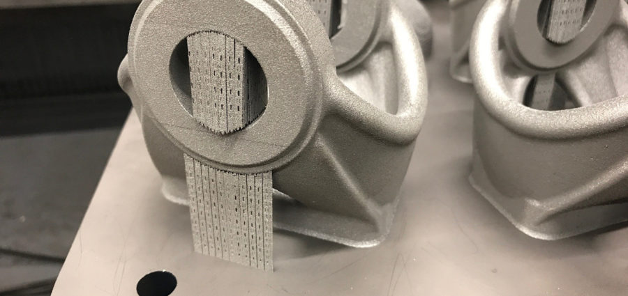
Many metal Additive Manufacturing technologies require support structures that are created during the printing process to improve heat conductivity and prevent distortion of the part. The need for support structures leads to certain design and process limitations. The type, amount and even material of supports as well as the rule set to apply them greatly differ depending on the considered process.

In PBF technology, support structures are required for numerous reasons. They are placed below overhangs of parts to allow for a build-up of material on consecutive manufacturing layers. Since powder acts as a heat insulator, supports are needed to dissipate the heat from the exposed area and avoid balling of molten material. Part overhangs with an angle below 45° with respect to the building platform have to be supported. The exact angle might differ depending on the material and process parameters.

In LB-PBF the powder bed does not possess a mechanically stabilizing property, therefore support structures fix the part to the building platform to avoid undesired part movement during coating process with new powder. Furthermore, the support structures have to counteract heat-induced residual stresses and prevent deformation of a part. Similar to other welding processes, residual stresses are formed during the material fusion and solidification. For some parts it may be beneficial to use solid structures that withstand the load from residual stresses or place the parts directly onto the building platform.

To reduce the efforts of support removal and allow more complex geometries LB-PBF OEMs are working on improved process strategies to realize support free manufacturing of lower angles. Most prominently VELO 3D introduced  a LB-PBF system and process concept, that significantly reduce the need for support structures. The system uses a combination of a proprietary recoating system and a software to optimize exposure. The aim is to minimize inherent stresses during the process and optimize the heat management, which results in fewer supports. Other LPBF suppliers like EOS and SLM SOLUTIONS have also introduced solutions, many based on optimized exposure strategies to build overhangs support free.

Metal Laser Powder Bed Fusion parts on baseplate

Thin and easy to remove support structure.

Solid connection of the part. Radius to prevent cracking by residual stress. 

Supports broke during printing process due to residual stresses.

The supports are removed after the building processes. The respective part end of the support structure is typically tapered. High notch stresses near this part interface lead to a predetermined breaking point and facilitates the support removal. The supported surface has to be post-processed to remove support remnants. Supports should not be attached to surfaces where a subsequent machining is undesired or even impossible, such as for to lattice structures or other filigree features. Thus, the building direction and subsequent support is of a major importance during data preparation.

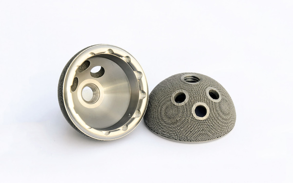
Sinter-based AM technologies and process chain

Sinter-based AM - a technology overview

Many different printing technologies - one sintering process

The sinter-based AM (SBAM) technologies have, as the name suggests, the sintering process in common. In this process, the printed green part is consolidated into a dense part and receives its final properties. The green part can be printed in advance using different technologies.They all have in common that metal powder is bound to the desired shape by a binder. The best-known printing technologies include Binder Jetting and Filament Material Extrusion.

In this section, you learn everything about the sinter-based AM  process chain and get an overview of the different printing technologies.

Goal and structure of this course

This course is aimed at engineers, designers and other professionals that are working closely with sinter-based AM technologies. The goal is to cover the most important aspects that will enable engineers and designers to fully grasp the capabilities and technical limitations of the printing technologies and the sintering process to succeed in technology selection and part design. Besides going through the course from the beginning until the end, this course can also act as a constant source of knowledge while working on AM projects. 

The course is structured into the following sections.

This section will start with an overview of the sinter-based AM process chain and its printing technologies, followed by a technology deep dive into the most important aspects of the BJT technology, followed by a closer look at the debinding and sintering step also including sintering simulation .

The second section will provide an overview of the different materials that are available as well as part characteristics that can be achieved with the BJT process and typical methods for quality assurance. Finally, several common defects in the BJT process are presented. 

The last section will act as a guideline for designers. Besides generally describing the process when designing for Additive Manufacturing, actionable restrictions and guidelines for the BJT process are provided. The final section will present several design examples from different industries. 

What you will find in this section

Sinter-based AM process chain

From digital model to finished part

Data preparation

Simulation to compensate the deformation during the sintering step, nesting of parts and definition of printing parameters

Printing

Through various printing processes, different feedstocks such as metal powders, filaments, pellets or dispersions are processed into green parts

Unpacking

Unpacking of fragile green parts needs to be done carefully and is typically a manual process.

Debinding

Debinding describes the process of removing the binder which results in a brown part

Sintering

To reach the structural integrity of a metal part, a sinter process is required. The powder particles fuse together to a coherent, solid structure via a mass transport that occurs at the atomic scale driven via diffusional forces.

The brown part shrinks ~13-21 % in each direction.

The process chain of sinter-based technologies differs from other AM Technologies. Especially the post-printing processes (debinding and sintering) are crucial to achieve the intended mechanical properties.

Technology principle

How does Binder Jetting work?

Binder Jetting is a powder based Additive Manufacturing technology in which a liquid polymer binder is selectively deposited onto the powder bed binding the metal particles and forming a green body.

The metal powder is applied to a build platform in a typical layer thickness of 40 µm to 100 µm. Subsequently a modified 2D print head apply a binder selectively onto the powder bed. Depending on machine technology a hardening or curing process of the binder is performed in parallel for each layer and/or at the end of the whole build. During the in-situ curing process a heat source is used to solidify the binder and form a solid polymer – metal powder composite.

Working Principle of Binder Jetting

Afterwards the build platform moves downward by the amount of one layer thickness and a new layer of powder is applied. Again, the liquid binder is deposited and hardened in the required regions of the next layer to form the green body. This process is repeated until the complete part is printed. After the complete printing process is finished the parts have to be removed from the “powder cake” meaning the surrounding loose but densified powder. To improve the removal of the excess powder from the green body often brushes or a blasting gun with air pressure are used.

To create a dense metal part the 3D printed green body has to be post-processed in a debinding and sintering process. Similar to the metal injection molding process BJT parts are placed in a high temperature furnace, where the binder is burnt out and the remaining metal particles are sintered together. The sintering results in densification of the 3D printed green body to a metal part with high densities of 97 % to 99,5%, dependent of the material.

Printing Technologies

Metal Binder Jetting

Binder Jetting is a powder based Additive Manufacturing technology in which a liquid polymer binder is selectively deposited onto the powder bed binding the metal particles and forming a green body.

The metal powder is applied to a build platform in a typical layer thickness of 40 µm to 100 µm. Subsequently a modified 2D print head apply a binder selectively onto the powder bed. Depending on machine technology a hardening or curing process of the binder is performed in parallel for each layer and/or at the end of the whole build. During the in-situ curing process a heat source is used to solidify the binder and form a solid polymer – metal powder composite.

Working Principle of Binder Jetting

Material Extrusion

Binder Jetting is a powder based Additive Manufacturing technology in which a liquid polymer binder is selectively deposited onto the powder bed binding the metal particles and forming a green body.

The metal powder is applied to a build platform in a typical layer thickness of 40 µm to 100 µm. Subsequently a modified 2D print head apply a binder selectively onto the powder bed. Depending on machine technology a hardening or curing process of the binder is performed in parallel for each layer and/or at the end of the whole build. During the in-situ curing process a heat source is used to solidify the binder and form a solid polymer – metal powder composite.

Working Principle of Binder Jetting

Mold Slurry Deposition

Binder Jetting is a powder based Additive Manufacturing technology in which a liquid polymer binder is selectively deposited onto the powder bed binding the metal particles and forming a green body.

The metal powder is applied to a build platform in a typical layer thickness of 40 µm to 100 µm. Subsequently a modified 2D print head apply a binder selectively onto the powder bed. Depending on machine technology a hardening or curing process of the binder is performed in parallel for each layer and/or at the end of the whole build. During the in-situ curing process a heat source is used to solidify the binder and form a solid polymer – metal powder composite.

Working Principle of Binder Jetting

Metal Selective Laser Sintering

Binder Jetting is a powder based Additive Manufacturing technology in which a liquid polymer binder is selectively deposited onto the powder bed binding the metal particles and forming a green body.

The metal powder is applied to a build platform in a typical layer thickness of 40 µm to 100 µm. Subsequently a modified 2D print head apply a binder selectively onto the powder bed. Depending on machine technology a hardening or curing process of the binder is performed in parallel for each layer and/or at the end of the whole build. During the in-situ curing process a heat source is used to solidify the binder and form a solid polymer – metal powder composite.

Working Principle of Binder Jetting