Design restrictions & guidelines – metal L-PBF
Design restrictions & guidelines
Design for AM guidelines are key for successful parts
Additive Manufacturing design is one of the major factors for the successful implementation of the technology. Today, most companies are familiar with the basics of the right design for Additive Manufacturing. However, technological advances have completely different process driven limitations and potentials that have to be considered.
What you will find in this section
Design guidelines
High design freedom only limited by support structures
Regarding the design of parts fabricated with L-PBF technology, several principles have to be considered. Overhanging structures must be braced by support structures to enable heat dissipation and to avoid part deformations due to internal stresses.
Horizontal holes or channels have to be supported, too, or designed in a drop shape to avoid overhangs. Minimal wall-thickness depends on the optical resolution of the machine and parameter set. In general, a wall-thickness of more than 0,5 mm is recommended.
Theoretically, the maximum part size depends only on the build volume of the machines and is in the range of several decimeters in all directions. In practice, process stability and resulting residual stresses in massive metal parts have to be considered and may limit the component size.
When designing a part for L-PBF, the guidelines presented in this chapter can act as a general rule of thumb for designers. Once it comes to the actual printing of the part, machine- and process-related aspects then need to be considered and might give additional design freedom or add restrictions.
-
Typical part size
Typical part sizes range from 15 mm to 300 mm. Large parts can cause complications due to distortion.
-
Resolution
Layer thicknesses are in a range of 0.025 – 0.09 mm. The typical geometrical accuracy is ± 50 µm.
-
Surface roughness
The surface roughness depends on the layer thickness and the material. Typical Ra values are between 5 – 10 µm.
-
Wall thickness
Thick walls can cause porosity. Typically walls between 1 – 10 mm are recommended. Sudden jumps in thickness should be avoided.
-
Hollow bodies
Hollow bodies are possible as long as the support material and residual powder can be removed.
-
Shrinkage
There is not shrinkage that has to be considered.
-
Distortion
Residual stresses can cause distortion. Especially for overhangs and large parts, distortion can be a problem. Advanced simulation tools are available.
-
Supports
Usually overhangs of 45° can be build support free. In some cases, process modifications allow for even lower overhangs up to 10°.
-
Lattice
Lattice structures are possible and easy to achieve with LPBF.
Stresses
Process induced stresses foundation for most design guidelines
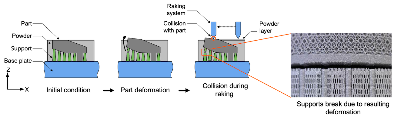
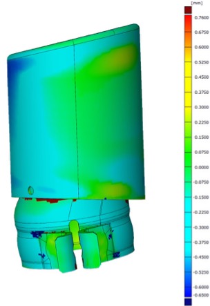
Thermally induced stresses lead to part deformation and cracks and should thus be minimized. The graphic above shows how stresses lead to a deformation of the part from the support structures. This can both result in non-conformance of the part but can even lead to the recoater collisioning with the part and thus interrupting the entire build job.
Stresses can be minimized by changing the design of the part, changing the process parameters, designing more massive support structures or by changing the part orientation. Simulation of the stresses prior to the build job can avoid costly failures.
Dimensional limitations
Dimensional limitations for AM design
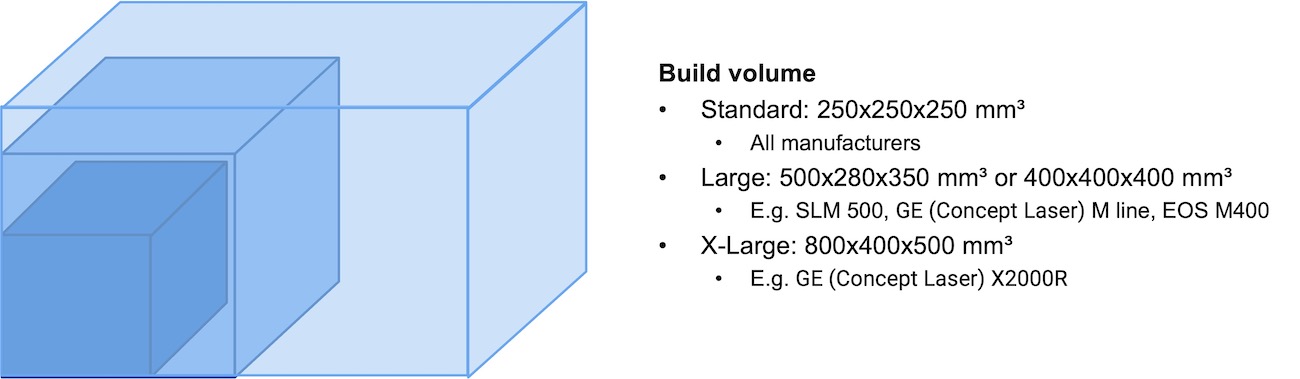
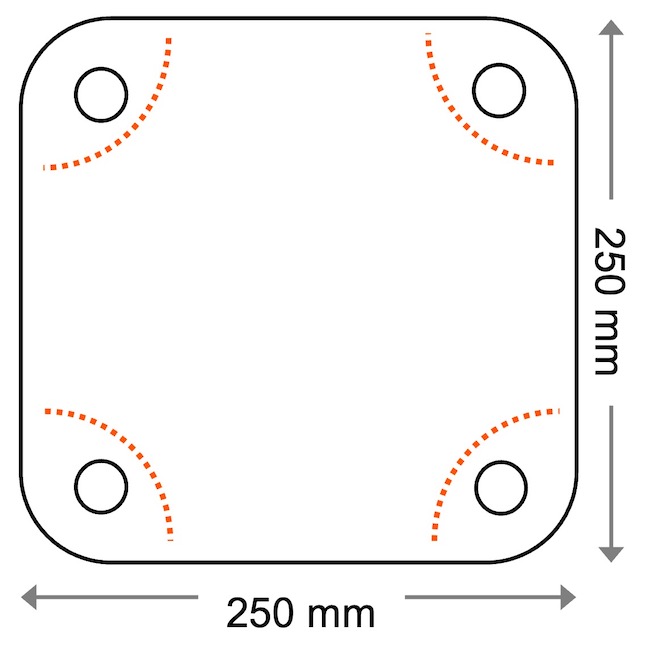
Part dimensions in L-PBF are primarily restricted by the available machine technology. While the standard machine size is around 250 x 250 x 250 mm³, selected models reach up to 1m in each dimension. Parts fabricated with L-PBF are typically significantly smaller. Multiple parts fit into the build volume to be manufactured simultaneously during one build job. However, there are applications which take up the whole building envelope.
Not only the build volume limits the upper limit of part dimensions in PBF. Residual stresses and other process related factors may restrict the part size, the wall thickness or the feasible building orientation.
Another aspect to consider when positioning parts in the build chamber are mounting holes. The picture on the left illustrates the 4 mounting holes of the build platform where no parts can be positioned.
Supports and overhangs
Supports restrict freedom of design
The L-PBF process requires support structures that are created during the printing process, which leads to certain design and process limitations.
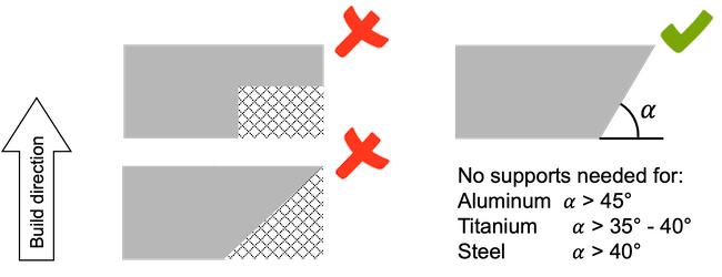
Support structures are required for numerous reasons. They are placed below overhangs of parts to allow for a build-up of material on consecutive manufacturing layers. Since powder acts as a heat insulator, supports are needed to dissipate the heat from the exposed area and avoid balling of molten material. Part overhangs with an angle below 45° with respect to the building platform have to be supported. The exact angle might differ depending on the material and process parameters.
The powder bed does not possess a mechanically stabilizing property, therefore support structures fix the part to the building platform to avoid undesired part movement during coating process with new powder. Furthermore, the support structures have to counteract heat-induced residual stresses and prevent deformation of a part. Similar to other welding processes, residual stresses are formed during the material fusion and solidification. For some parts it may be beneficial to use solid structures that withstand the load from residual stresses or place the parts directly onto the building platform.
To reduce the efforts of support removal and allow more complex geometries, machine OEMs are working on improved process strategies to realize support free manufacturing of lower angles. Most prominently VELO 3D introduced a L-PBF system and process concept that significantly reduce the need for support structures. The system uses a combination of a proprietary recoating system and a software to optimize exposure. The aim is to minimize inherent stresses during the process and optimize the heat management, which results in fewer supports. Other machine suppliers like EOS and SLM SOLUTIONS have also introduced solutions, many based on optimized exposure strategies to build overhangs support free.
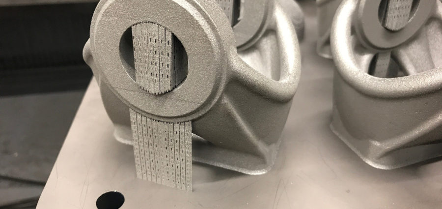
Thin and easy to remove support structure.
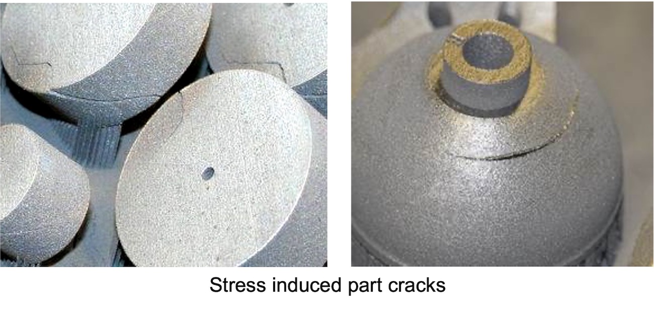
Solid connection of the part. Radius to prevent cracking by residual stress.
Supports broke during printing process due to residual stresses.
The supports are removed after the building processes. The respective part end of the support structure is typically tapered. High notch stresses near this part interface lead to a predetermined breaking point and facilitates the support removal. The supported surface has to be post-processed to remove support remnants. Supports should not be attached to surfaces where a subsequent machining is undesired or even impossible, such as for to lattice structures or other filigree features. Thus, the building direction and subsequent support is of a major importance during data preparation.
Additionally to manual or machining operations to remove support structures Austrian based company HIRTENBERGER ENGINEERED SURFACES developed an electro-chemical process aimed at automated removal. The process may offer a solution to reduce removal efforts and increase the design freedom due to the accessibility of the chemicals for support removal in channels and cavities.
Support design
When designing a part the goal is to reduce support structures as much as possible. They have several downsides since they increase post processing effort, surface roughness, manufacturing time and material waste. The pictures on the right illustrate from which angle support structures are required. The values on the right side depending on material should only be seen as rough guidelines.
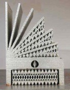
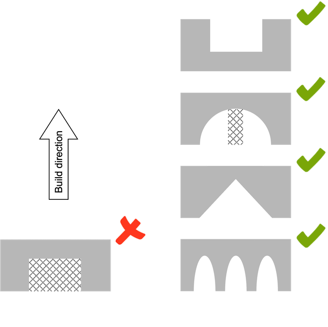
There are several ways to avoid support structures in case of overhanging surfaces. The initial arch design on the left side requires the entire downward facing surface to be supported. One easy solution would be to change the orientation by 180 degrees as displayed above. If this is not possible, a round arch would already lead to less support. Changing the shape into a triangle or several smaller arches entirely removes the need for support structures.
Feature size and thin walls
AM design for wall thickness, resolution and feature size
Minimal features are limited by the process. The minimum wall thickness, resolution and feature size are limited by the layer thickness in z-direction. In xy-direction, the resolution is a dependent on the laser spot size. In addition to such machine related factors, the minimum wall thickness is also restricted by the stability of the part. For processes that result in high temperature gradients, parts will deform, if walls are designed too thin.
As a rule of thumb, thin walls lower than 0.5 mm should be avoided. Large thin-walled skins can be supported through stiffening structures such as honeycombs, stringers or lattices.
In theory no upper limit for wall thicknesses exists as long as a stable process can be achieved. However, a large area of molten material per layer causes smoke residue that may negatively impact the process and resulting material properties. Also, residual stresses of the resulting bulky part may play a limiting role.
Material removal
Accessibility necessary for supports and material removal
Laser Powder Bed Fusion is considered to be a resource efficient production process with little material waste. The required input material volume is equal to the part volume. However, the complete build chamber needs to be fully filled with a powder bed to enable printing of the part. Unused powder can be recycled and is removed at the end of a printing job.
The powder bed is only loosely packed. By tilting the build platform during unpacking the powder will flow away. Alternatively, the powder can be brushed or vacuumed into a container. Hollow structures that are filled with powder must always be designed with an opening to make powder removal possible.
Especially for larger L-PBF machines with building platforms of 300 mm or more, manual handling of the platform during unpacking becomes infeasible. Due to the high weight, cranes or trolleys may have to be used to lift the platform out of the machine. To improve the powder removal from large build jobs and reduce manual efforts as much as possible unpacking stations with vacuum assistance have been introduced by the machine OEMs. Over the past few years, additional companies pushed into the market offering periphery machinery. One example is company SOLUKON, who developed a handling station to manipulate the whole build platform with parts to remove all powder from cavities. Through a mechanic in an enclosed and inert chamber it allows for automated powder removal from the parts by making use of gravity. The rotation and vibration can be individually programmed to achieve best results even for the most complex internal channel geometries.
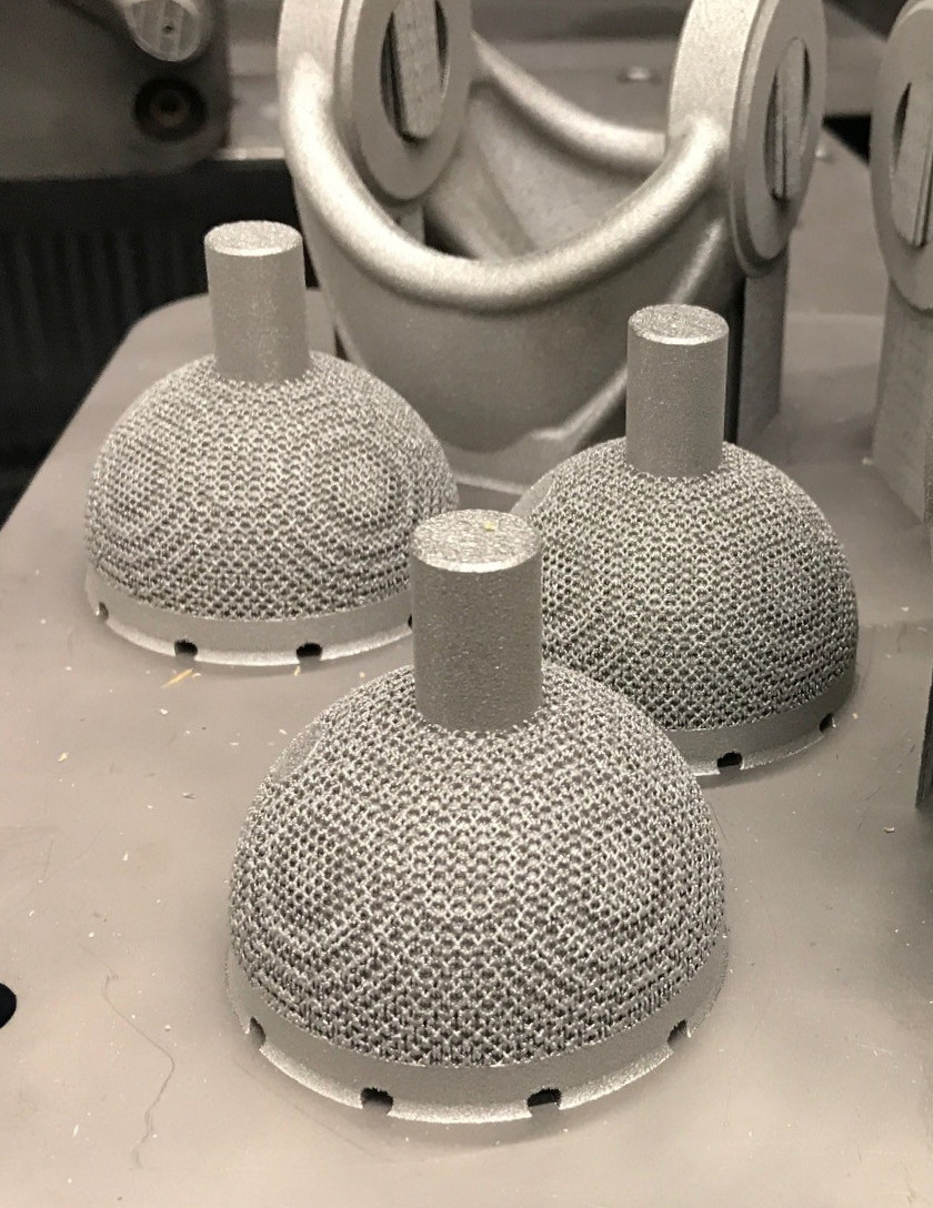
Holes to remove the powder within the hip cup before the EDM process.
Surface effects
Surface roughness due to staircase effect and weld beads
The final part surface has a large impact on the functional properties and its use. Design considerations should not only be focused on the printing process. It also needs to be considered when it comes to decide on post-processing steps and how to perform these on the printed part. The as-built quality of the printing process influences the type and extent of post surface treatment.
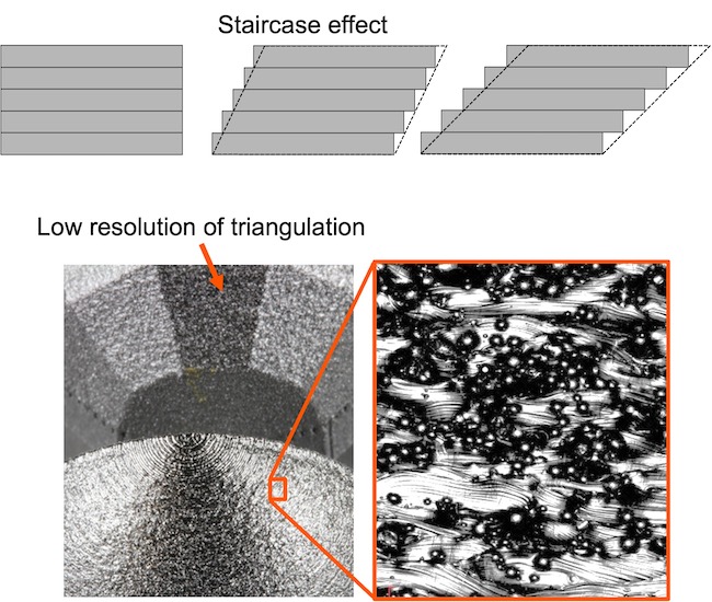
The condition of the as-built part surface is influenced by several process inherent factors. For small layer thicknesses, high process resolution in combination with small powder particle distribution results in a smoother surface. For the opposite, large layer thicknesses, low resolutions and coarse powder particles, a high surface roughness is expected. A high surface roughness can be desired in some cases, for example in medical applications, where it facilitates bone ingrowth.
A low resolution can also be caused by a too low triangulation of the STL file. As a rule of thumb, the as-printed surface roughness is Rz: 80 – 140 µm and Ra: 13 – 25 µm. While different values can be achieved for different orientations, downward-facing surfaces usually display the highest roughness.
For the majority of applications, a surface treatment is required. In general, the AM user is spoilt for choice out of the multitude of conventional surface processing technologies for metal materials. While functional surfaces are usually CNC machined, grinding and blasting techniques may be an option to also improve undefined freeform surfaces.
In 2018 and 2019, the metal Additive Manufacturing industry experienced market entry from established companies that rebranded their service and machinery portfolio to specifically target the post-processing of net-shape AM parts. An example is company RÖSLER OBERFLÄCHENTECHNIK that was already providing surface treatment equipment to AM users but decided to offer dedicated products to the AM market through their new brand AM SOLUTIONS. Company AALBERTS similarly founded the spin-off AALBERTS ADDITIVE MANUFACTURING to offer post-processing services such as surface or heat treatment targeted at AM parts and users.
Holes and channels
Creative alternative design solutions to avoid support for channels
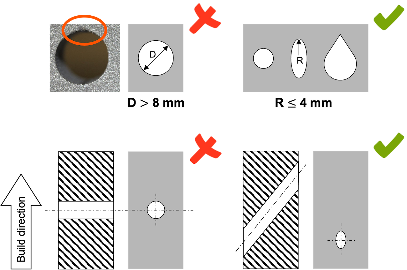
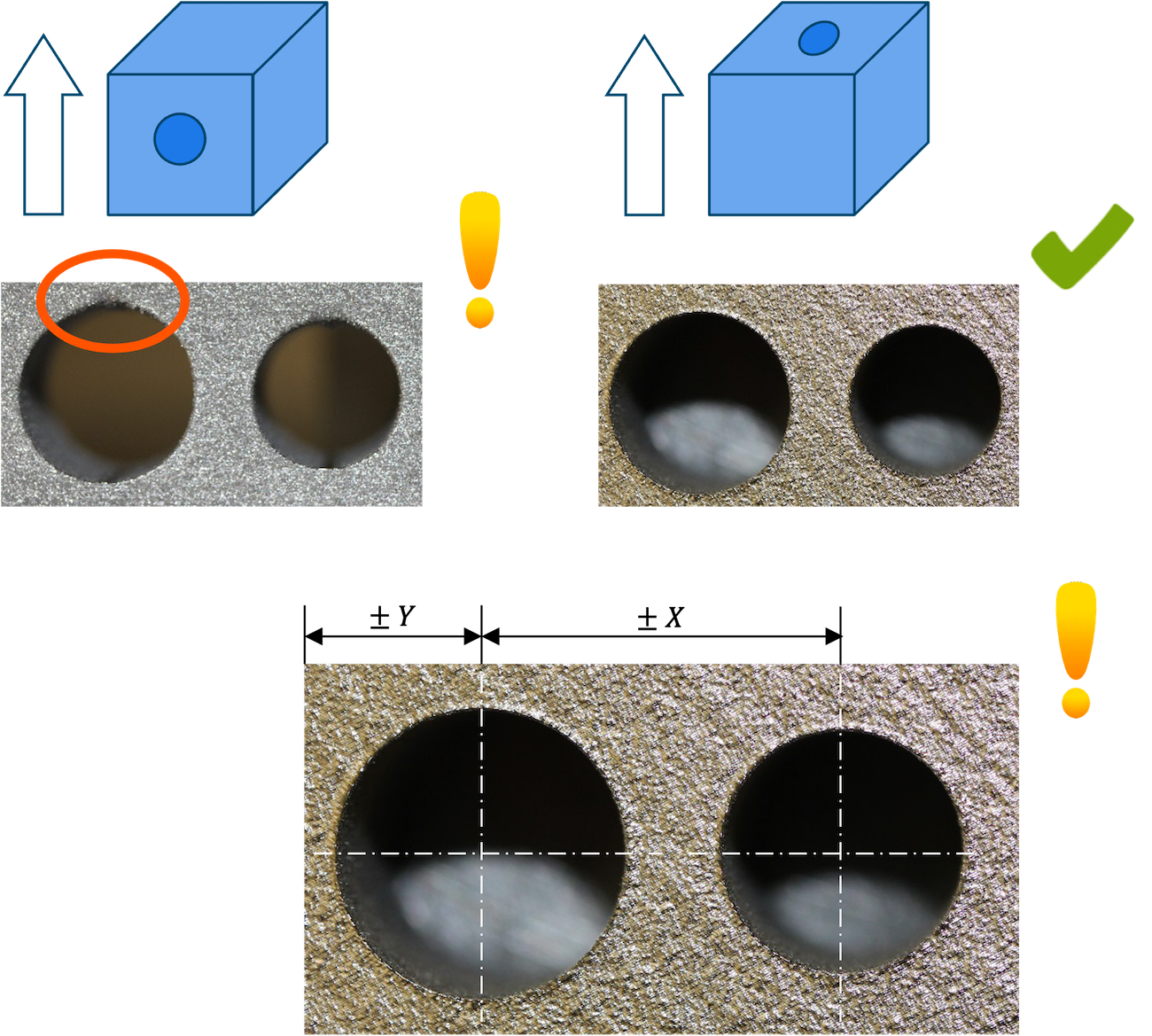
Holes and channels are a typical design feature that requires a designer’s attention. As a rule of thumb, holes with a diameter smaller smaller than 2 mm should be avoided since powder adhhesion leads to clogged channels. Holes with a diameter below 8 mm are possible without support structures.
There are different ways to around these challenges. Again, one possible solution is changing the orientation. Alternatively, the shape of the hole can be changed from round holes to e.g. oval or teardrop-shaped holes.
The form tolerance of “vertical” features lacks accuracy due to insufficient melting at upper edges. The form tolerance of horizontal features is ± 50 µm for a stable process
The positional tolerance of holes highly depends on the shrinkage, distortion and process stability. High precision features have to be post processed and bore holes should be closed to avoid misguiding of the tool during post processing.
Accuracy
Achievable accuracy depending on a variety of factors
The achievable accuracy strongly depends on the distortion due to residual stresses, the build temperature and optimized shrinkage compensation and the suitability of the design. Generally, the distortion is small for aluminium, medium for steel and high for titanium. As a rule of thumb, the typical geometric accuracy is ± 50 µm. The dimensional accuracy for prototypes is < 3 % and for serial production 100 – 500 µm.