Powder Laser Energy Deposition
Powder Laser Energy Deposition
Additive Manufacturing based on established welding technology
Powder Laser Energy Deposition (ED), also known as Laser Metal Deposition (LMD) is a welding technology used for many years. Recently the technology is adopted as an Additive Manufacturing technology by system integrators and off-the-shelf system providers. In this section you learn about the background of Powder Laser ED.

What you will find in this section
Technology principle
How does Powder Laser Energy Deposition work?
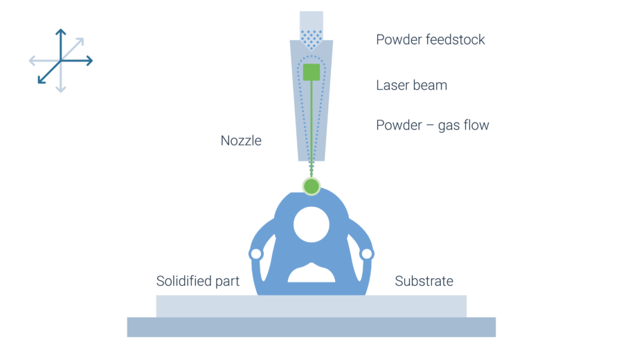
Powder Laser ED, also sometimes referred to as Laser Metal Deposition (LMD), is a welding technology in which a laser forms a melt pool on a metallic parts’ surface. At the same time a powder feedstock is blown through a nozzle into the process zone, where it is preheated by the laser and then absorbed by the melt pool. After solidifying, raised welding beads remain. By repeating the process, the welding beads are built on top of each other and a three-dimensional structure is formed. Powder Laser Energy Deposition is a sub-group of the Direct Energy Deposition technologies. Typical for DED technologies is the high deposition rate of material, which is locally applied to form near net-shape blanks.
Processing unit with multi axis system
The laser beam and the powder supply are combined in a single processing unit, the working head. In a multi axis system typically the working head as well as the substrate plate on which the part is built are fixed to some kind of motion system. The supplier BEAM uses a gantry with five continuous axes for realization of the processing unit’s motion. TRUMPF offers Powder Laser Deposition systems in which the processing unit head is attached to a robot arm. For rotationally symmetric parts, substrate plates can also be fixed to a rotation-tilt table.
Hybrid Powder Laser Deposition technology
In a hybrid system, such as from supplier DMG MORI, the Powder Laser Deposition process is combined with a subsequent CNC machining. The build platform is movable around two axes and the process unit head around three axes. After a section of part or the complete part is built, a milling head is extended and finishes the as-printed parts’ surfaces.
Pre- and post processing
High efforts for data preparation for DED technologies
Before the actual build process can start a relatively complex data preparation takes place which is very similar to data preparation for CNC machines.
When designing the part, the orientation and possible integration of the substrate has to be considered. Then, offsets between the deposition tracks are defined. Support structures are not necessary, since parts are directly deposited on a substrate. However, printing overhangs without tilting the build platform is only possible up to an angle of about 20° degrees. Thus, to manufacture any overhanging structures, axes movement has to be considered in order to manipulate the part orientation with reference to the processing unit.
The toolpath and the subsequent processing are dependent on the type of geometry, that needs to be created. The processing strategy and its toolpath are programmed individually for each type of geometry. For preparation of this task, the part is segmented into individual sections using a CAD software. So far, only semi-automatic CAM solutions for assigning a processing strategy and toolpath to a segment exist (for example from SIEMENS).
After the build job, parts are generally post-processed by a thermal treatment and machining. A detaching of the part from the build platform does normally not take place as the build platform is part of the geometry. Since the Powder Laser Deposition technology includes a welding process with high temperature gradients, residual stresses occur. To avoid deformation during processing, the substrate requires strong clamping fixtures. The stresses are removed in a subsequent heat treatment. For increasing the surface quality of the part, machining of the surface takes place.
Development history
Long history in cladding applications
Powder Laser Energy Deposition is known as a coating and welding technology for several decades. The process is well-established and common throughout industries for cladding of metallic surfaces and minor repairs. The technology has been field of interest for research institutions and other R&D activities for decades. Additional to process development and material qualification, specialized working heads with multiple nozzle shapes have been developed for specific applications.
First industrial additive applications have been the repair of turbine blades. The worn and damaged tips of the blade are cut off and Powder Laser Deposition is used to re-apply the material. Recently the technology was adapted as an Additive Manufacturing technology by system integrators and off-the-shelf system providers more widely. Besides repair and part individualization the technology is more and more used for the production of large near net-shape blanks. Today, the digital data preparation represents the major hurdle for a faster adoption of the technology. The pre-processing steps require a lot of knowledge, manual input and programming. Also, extensive testing of build strategies and cooling times are necessary for each new part geometry.
Supply chain
Integrators and solution providers set heterogenous supply chain
Customers interested in Powder Laser Energy Deposition have two possibilities for purchasing the machine technology. On the one hand system integrators exist, that use working heads that are integrated into handling and machine technology specifically designed for one application. Along with complete manufacturing systems, DM3D offers this kind of system integration. On the other hand, there are suppliers, that provide turn-key solutions that include machine technology, processing settings as well as feedstock material. Examples of such suppliers are BEAM, DMG MORI and TRUMPF.
Customer-specific integrated solutions come into play in case of applications with high lot sizes that are produced over a longer period. Integration is more cost-efficient but connected to losses in flexibility. Within Additive Manufacturing, flexibility and individualized parts are important selling points. Therefore, system providers with flexible solutions are expected to find a market.
Advantages and disadvantages
Powder Laser Energy Deposition technology based on machining and coating history
High build rate
The build rate in cm³/h is 2 – 3 times higher compared to L-PBF.
Flexible machine technology
Multiple suppliers of working heads and/or completely integrated turn-key systems offer solutions for a wide range of different applications.
Highest resolution for DED technologies
Specialized working heads allow for “micro” applications with resolutions below 1 mm.
High effort for data preparation
CNC based tool path programming is time consuming and requires experience.
Cooling time decreases productivity
Depending on part geometry cooling phases to prevent overheating can make up to 50% of the manufacturing time.
Process video
The technology in action
Below you can see a video of the Powder Laser ED process from Italian machine manufacturer BeAM. They use powder as a feedstock and a laser to melt the powder.

By loading the video, you agree to YouTube's privacy policy.
Learn more


