Wire Arc Energy Deposition
Wire Arc Energy Deposition
Additive Manufacturing based on wire-based welding technology
Wire Arc Energy Deposition, also known as Wire Arc Additive Manufacturing, is based on conventional wire based welding processes such as MIG, MAG and TIG welding. Due to its simplicity and low cost input material, the technology promises very high build rates at low cost. However, to achieve the full flexibility that Additive Manufacturing claims, further development efforts in data preparation are still necessary.

What you will find in this section
Technology principle
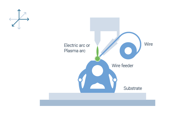
How does Wire Arc Energy Deposition work?
Wire Electric Arc and Wire Plasma Arc Deposition are Direct Energy Deposition processes based on conventional wire-based welding such as MIG, MAG, TIG and plasma welding. For Wire Arc Deposition, existing, off-the-shelf welding equipment can be used. The welding power is provided by an electric or plasma arc that melts the feedstock to create the weld bead. The wire is fed with a conventional wire-feeding system to the working area. The motion of the welding torch can be provided either by a robotic or a gantries system. An Additive Manufacturing process is achieved by welding beads next and on top of each other until a three-dimensional part is built in a desired geometry. Wire arc deposition technologies have a comparatively high deposition rates of material within the group of DED technologies. Wire Arc Deposition is almost always used to form near net-shape blanks.
Wire Electric Arc
A first type of machine technology is Wire Arc Deposition that can be further distinguished into processes that resemble MIG/MAG or TIG welding processes. Using the process type based on MIG/MAG welding, the wire functions as the consumable electrode that is passed coaxially through the welding torch. With ignition of the arc the tip of the wire melds of and drops into the meld pool on the workpiece surface. Unlike MIG or MAG, TIG based processes use a non-consumable electrode. The arc is created between the electrode and the workpiece surface while the wire is fed into the meld pool from the side. Therefore, an additional external wire-feed machine is required.
Wire Plasma Arc
The second process variant is Wire Plasma Arc Deposition in which a main arc is formed between a non-consumable tungsten electrode and the workpiece. The electrode is positioned within the plasma torch consisting of a nozzle through which a plasma gas, usually argon, passes and a collet for the electrode. Furthermore, a second so-called pilot arc, burns between the gas nozzle and the electrode. The argon is heated by the pilot arc until it converts into an ionized state. The welding wire is fed from the side by an external wire feed system. Due to the high energy plasma stabilizing the electric arc, very precise welding beads can be generated.
Pre- and post processing
High efforts for data preparation for DED technologies
Before the actual built process can start a relatively complex data preparation takes place which is very similar to data preparation for CNC machines.
When designing the part, the orientation and possible integration of the substrate has to be considered. Then, offsets between the deposition tracks are defined. Support structures are not necessary, since parts are directly deposited on a substrate. However, printing overhangs without tilting the build platform is only possible up to an angle of about 10° degrees. Thus, to manufacture any overhanging structures, axes movement has to be considered in order to manipulate the part orientation with reference to the processing unit.
The toolpath and the subsequent processing are dependent on the type of geometry, that needs to be created. The processing strategy and its toolpath are programed individually for each type of geometry. For preparation of this task, the part is segmented into individual sections using a CAD software. So far, only semi-automatic CAM solutions for assigning a processing strategy and toolpath to a segment exist (for example from SIEMENS).
After the build job, parts are generally post-processed by a thermal treatment and machining. A detaching of the part from the build platform does normally not take place as the build platform is part of the geometry. Since the Wire Arc Deposition technology includes a welding process with high temperature gradients, residual stresses occur. To avoid deformation during processing, the substrate requires strong clamping fixtures. The stresses are removed in a subsequent heat treatment. Due to the low resolution and rough and wavy surface structure a machining operation to finish the part surfaces has to take place.
Development history
Standard welding processes are the basis
The underlaying technology principle, a welding process based on the combination of an electric arc as heat source and wire as feedstock, was already patented in 1920. Besides joining to metal sheets has mainly been used to perform local repairs on damaged or worn out components. For Additive Manufacturing purposes, Wire Arc Deposition has been investigated since the ‘90s.
Today, the main challenge is to further develop the digital process chain. Especially complex, overhanging structures are currently challenging, since tilting of the weld torch for fabricated angled structures has influence on the process behavior and leads to deviations of the deposited weld bead. To maintain a uniform weld bead morphology, a constant travel speed of the welding torch is required. However, at the turning points of a geometry, the welding robot or gantry system has to slow down. Consequently, heat accumulations and humps may form in these regions that lower material quality and increase the effort for post-processing or even interrupt the process due to collision of the tool with the part. Therefore, suppliers focus on automated solutions for process control including heat monitoring so that parts remain near net shape even at turning points.
Supply chain
Off-the-shelf systems expand range of former application specific systems
Machine technology for Wire Arc Deposition is mostly specific to an application or application group. Some users have even developed and built their own machine technology to meet the highly induvial requirements. By using off-the-shelf welding equipment and robots for positional manipulation, the entry barrier in terms of investment is rather low.
Today’s suppliers of turn-key systems focus their efforts on specific industries. For example, machines from the supplier NORSK TITANIUM are optimized to meet the requirements in the aerospace industry. Besides titanium, also nickel-based alloys, tool steel or stainless can be processed. In recent years, GEFERTEC started to develop a flexible Wire Arc Deposition machine technology suitable for multiple kinds of applications.
Wire feedstock can be procured from traditional welding material sources. The wire is available in multiple alloy compositions and at a highly price competitive level.
Advantages and disadvantages
Wire Arc Energy Deposition with highest deposition rate
High build rate
Deposition rates of up to 4 kg/h are possible.
Low cost
Simple process and cheap input material.
Large parts possible
The part size is almost unlimited.
Data preparation very effortful
Complex geometries with angled walls are currently still challenging.
Low resolution
Manufacturing of small parts is not economical.
High thermal gradients
Thermally induced stresses can lead to deformations and must be removed during post processing.
Process video
The technology in action
Below you can see a video of the Wire Arc Energy Deposition process from German machine supplier GEFERTEC.

By loading the video, you agree to YouTube's privacy policy.
Learn more
After gaining a brief overview of Directed Energy Deposition, you can dive deeper into process characteristics as well as typical applications of the process by clicking on the topic below.


