Electron Powder Bed Fusion (E-PBF)
Electron Beam Powder Bed Fusion
Runner-up to Laser Powder Bed Fusion
In the shadow of L-PBF, Electron Beam Powder Bed Fusion (E-PBF) developed as a major technology for certain industries and applications such as medical devices in form of hip cups for bone replacement. Learn all about the state of the art of E-PBF in this report section, the advantages of the technology, further developments, and expected new market entrants of suppliers.

What you will find in this section
Technology principle
The working principle of Electron Beam Powder Bed Fusion
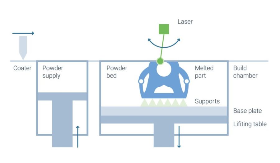
Electron Beam Powder Bed Fusion (E-PBF) is a powder based Additive Manufacturing technology in which the powder is melted by exposure with an electron beam.
The powder material is applied by a leveling system in a predefined layer thickness to a substrate plate fixed on a build platform. Different from laser beam powder beam fusion the powder bed is heated before the melting process by exposure with the electron beam at low intensity. During this pre-heating step the beam is widened and directed onto the powder until is has reached a sufficiently high temperature. For Ti-6Al-4V material, powder bed temperatures are in the range of about 700 to 800 °C. For other materials, such as CoCr or titanium aluminides this pre-heating temperature may even be higher.
After pre-heating, the building process starts. The electron beam is deflected by an electromagnetic field which, unlike the mirror deflection systems used in L-PBF machines, has no mass and no inertia. Thus, an instantaneous deflection of the beam is possible. With only one beam multiple weld pools can be maintained at the same time and increase productivity.
Transfer of kinetic energy of the mass-carrying electron particles at impact into the powder bed lead to heating of the powder above melting temperature, which fuses selectively. After the completed exposure of one layer, the build platform is moved down by the amount of the layer thickness and the next powder layer is applied. The process described is repeated until the entire component geometry is generated. In a subsequent step the unexposed powder must be removed. Typically, in E-PBF, the surrounding powder interlocks and forms a powder cake due to the energy introduced during the preheating. This powder cake is removed by blasting. Also, channels and internal structures have to be mechanically freed from powder
Machine technology
Electron Beam Powder Bed Fusion machine components
The basic components of E-PBF system technology are electron beam source, electro-magnetic elements for beam shaping and guiding as well as a building chamber with a lifting table and powder feed system.
A high voltage unit of 60 kV accelerates electrons emitted from a heated filament or crystal. The total output power of the electron beam gun ranges typically in between 3 to 6 kW. Electro-magnetic fields shape and focus the electron beam similar to optical lenses. The use of electro-magnetic fields for beam deflection allow for quasi-instantaneous repositioning of the beam.
The build chamber is required to be under vacuum to avoid coupling of the electron beam into atmospheric particles. Drawing the vacuum prior to process initiation takes about 30 to 60 minutes. Colibrium Additive/GE uses a so-called controlled vacuum by carefully adding the process gas helium to improve process stability and heat convection. Cooling of the build under vacuum before opening the machine requires around 1 to 4 hours.
Machine build volume sizes range today from 200x200x180 mm up to a diameter of 350 mm with a height of about 400 mm.
Development history
Electron Beam Powder Bed Fusion and its Swedish heritage
The technology was mainly driven by Swedish company ARCAM, with its development beginning around the turn of the millennium. In 2016, ARCAM was acquired by US based company GENERAL ELECTRIC (GE). ARCAM/GE secured key intellectual property in the form of patents, making the market entry for other companies difficult.
In 2007, LIMA used ARCAMs E-PBF technology to produce and market a medical hip-cup made out of biocompatible titanium alloy Ti-6Al-4V. Today, more than 100,000 of these medical implants have successfully been implanted. Many other medical companies followed suit and established E-PBF as technology for medical devices. Other industries such as aerospace discovered advantages using the high temperature process of E-PBF and used the technology to produce turbine components out of titanium aluminides, at that time inherently difficult for L-PBF. Today, aerospace and turbine industry also uses nickel base alloys and other materials with E-PBF.
The machine technology evolved over time. Temperature induced inaccuracy was countered by improved mechanical stability. Increase of longevity of the electron beam generating consumable was achieved by switching from filaments to crystals. The process stability improved greatly by employing sensors to detect powder blowouts (“smoke”) or calibration process. Additionally, productivity, build envelope size and high temperature processing have been major development foci.
Recently multiple companies entered the market or announced machine developments. FREEMELT and WAYLAND ADDITIVE have both introduced an E-PBF in 2019 and 2021. Additionally, PRO BEAM, JEO and other companies have recently launched new machines. The broader availability of suppliers and increased development of new materials accelerates its development,
Supply chain
Near-monopoly supply chain for Electron Beam Powder Bed Fusion
The installed base of machines for E-PBF and peripheral equipment for industrial use has been dominated by a single source, ARCAM/GE. To reinforce this dependency, ARCAM/GE sells its machines with “nearly closed” systems and corresponding parameter sets tailored to their powders. The acquisition of the large titanium powder producer AP&C by ARCAM/GE in 2014 further solidified their position as the main EB-PBF powder supplier. Although powder meeting the required specifications can be sourced from independent suppliers, many customers continue to rely on the established and well-supported supply chain offered by ARCAM/GE.
In contrast, FREEMELT provides an open E-PBF machine, designed specifically for research facilities and universities, enabling users to set and customize parameters and process behavior. This approach encourages experimentation and innovation, offering a more flexible alternative to the closed systems of ARCAM/GE.
The market strategies of new entrants like WAYLAND ADDITIVE, MITSUBISHI ELECTRIC, and JOEL remain uncertain. However, their entry into the market signals a potential shift, challenging ARCAM/GE’s monopoly-like position. The speed and success of these new players in breaking the established dominance will depend on their ability to meet industrial requirements and offer competitive solutions.
Advantages and disadvantages
Lack of supply chain hindering high adoption rate
The high density and good mechanical properties of parts manufactured via E-PBF are the main advantages. The possibility of stacking parts in the build chamber enables the production of bigger lot sizes and makes production more efficient. E-PBF is a single-stage production. A recycling of the unexposed powder is possible, however, due to formation of the powder cake, a more extensive treatment of the powder is necessary. As a result of preheating the powder bed, low temperature gradients occur during the process, and only minor internal stresses develop.
Restrictions are mainly the low degree of dissemination of the technology and the small selection of available qualified alloys. The freedom of design is limited due to formation of the powder cake that is difficult to remove from channels and internal structures.
Low cost
Compared to L-PBF lower cost due to build chamber stacking (for selected applications) and low cost powder.
Less supports and high process temperature
Less supports and inherent stress issues due to high build chamber temperature.
High density of parts
High density and good material properties of parts manufactured via EB-PBF.
Complex process
Single source and little public knowledge leads to complex process and development efforts.
Powder removal
High build temperatures lead to hard powder cake which can be difficult to remove.
Limited materials
Focus on specific industries hinders development of wide material range.
E-PBF Process Video
The technology in action
Below you can find an explanative video of the E-PBF process by Oak Ridge National Laboratory if you would like to find out more about the process.

By loading the video, you agree to YouTube's privacy policy.
Learn more
After gaining a brief overview of Electron Beam Powder Bed Fusion, you can dive deeper into process characteristics as well as typical applications of the process by clicking on the topic below.


