Materials for metal L-PBF

Materials

L-PBF material variety

For L-PBF a large variety of alloys is commercially available. The most important prerequisite is a good weldability. Furthermore, the material must be available as a powder with a suitable particle size distribution. The powder fraction is system and process specific and differs between about 20 µm to 60 µm. With an adaptation of process parameters larger as well as finer powder fractions are possible, too. Very fine powder fractions tend to agglomerate during handling and coating due to extremely fine dust particles in the distribution and should be avoided.

Typical alloys processed with L-PBF are Ti-6Al-4V, CoCr, stainless and tool steels, nickel-based superalloys, aluminum alloys and also precious metals. High purity copper is difficult in processing with today’s machine systems as the available laser wave lengths is only poorly absorbed.

Material overview

Map of LPBF materials

Materials for applications

Major AM materials in today's applications

For certain applications some Additive Manufacturing alloys are predominantly used.

The most common materials in medical industry are CoCr and titanium alloys. CoCr exhibits excellent chemical and wear resistance and has therefore been a widely used material in dental industry since decades. In particular, dental copings are made of CoCr. Conventionally the material is centrifugal casted or blanks CNC machined. The copings are cemented into the jawbone and veneered with ceramics.

Endoprostheses for bone replacement, such as hip replacements or knee joint arthroplasty, are made of Ti-6Al-4V, because of its bioinertness and osseoconductivity. The implants are traditionally fabricated by CNC machining.

In both cases, the use of Additive Manufacturing facilitates and enhances the production process. The additively manufactured implants achieve similar mechanical properties to the cast and machined counterparts. At the same time cost-intensive production steps such as additional coatings at the bone-implant interface to facilitate bone ongrowth can be omitted. The AM process enables direct manufacturing of lattice structure that are highly osseoconductive.

In turbine and aviation industry titanium and nickel-based alloys are widely in use. Titanium alloy Ti-6Al-4V is mostly applied in lightweight constructions due to its high specific strength. Alloy 718 is characterized by high thermal stability and utilized as a high-temperature material.

Tool steels are applied for Additive Manufacturing of molds, jigs and manufacturing tools.

Aluminum alloys are used for prototyping and for manufacturing of spare parts of former cast aluminum parts. For automotive industry high-strength alloys (6000, 7000) are of great interest. These are still difficult to process by LB-PBF and thus extensively studied.

Powder production processs

Gas atomization remains the dominant powder production process today

Powder is the most widely used feedstock in the AM industry. Even though the consumption has constantly increased over the years, volumes are still significantly lower when compared to traditional feedstock such as bar materials or wires.

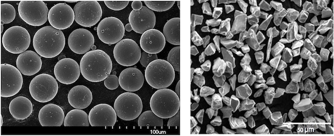
For fabrication of metal powders, the alloy melt is rapidly cooled in an atomization process to form powder particles. Here, two variants can be distinguished, gas atomization and water atomization. The molten metal is poured into an atomization chamber where the melt is fragmented into droplets by high-speed gas or water jets. When the droplets have reached the bottom of the chamber, they have solidified. The main factor which differentiates water atomization from gas atomization is the resulting particle shape. Water atomized powder is highly irregular in comparison to gas atomized powders. Gas atomized powders in contrast have a spherical shape. The heat transfer between the melt and the gas is low and allows the liquid material to form a sphere in flight before solidifying.

So far, mostly gas atomized powders are used for PBF. The spherical structure is believed to have a positive impact on packing density of the powder and the resulting density of the part. Moreover, it allows an even layer application due to its high flowability. Currently, the use of water atomized, irregularly shaped powders is also tested and first acceptable results are achieved.

For L-PBF typically particle sizes around 45 µm are used. Today, the powder is obtained by sieving out the powder fraction between 20 µm to 60 µm from the whole atomized production batch. Due to the additional atomizing and sieving process L-PBF powder is more expensive with prices between 40 EUR/kg to 70 EUR/kg. Current developments to increase the particle fraction will lead to further cost reductions in the future. 

Powder quality

Powder characteristics have an important influence on part quality

The characteristics of the powder play an important role in the LPBF process. Some of the most important factors that are typically controlled are the chemical composition, particle shape, particle size distribution, flowability and density

The particle shape plays an important factor. The L-PBF process works best for spherical particles with a smooth surface and no satellites as can be seen in the left picture. This ensures a good flowability and thus recoating behavior during the process. The particle share is typically inspected directly through a Scanning Electron Microscope, indirect through a hall flow meter or visually. 

Spherical particles with “smooth” surface & no satellites (left)
PSD comparison for virgin, 6th cycle and 12th cycle recycling for Ti-6Al-4V
Changing powder characteristics after 6 & 12 sieving cycles
Source: Seyda
Changing powder characteristics after 6 & 12 sieving cycles Source: Seyda

Powder that is used during the L-PBF process but does not end up in the part can be recycled and re-used for subsequent build jobs after a sieving process. The powder quality must be controlled since over time, e.g. through the sieving process or through storage, the powder characteristics will change. The chart on the left compares the particle size distribution (PSD) of Ti-6Al-4V for virgin powder with 6 and 12 times recycled powder. It can be seen that over time, the PSD changes a higher share of larger particles. The reason for this development is that small particles get caught in the filter during the build process and also adhere to bigger particles to form agglomerates. It can be seen in the pictures below the chart how the powder quality changes over time. 

In order to avoid changing material characteristics, typically recycled powder is mixed with virgin powder. By regularly refreshing re-used powder, a constant powder quality in terms of particle size distribution, oxygen content and other characteristics can be achieved. 

Material outlook

Custom AM materials and future developments

As production processes become established, the development of customized alloys for the respective processes follow. For example in traditional manufacturing, special casting alloys or alloys optimized for cutting and milling processes emerged. For the future of AM alloys, this development is expected, too. The material Scalmalloy provides a first example for an alloy developed and enhanced for Additive Manufacturing. Scalmalloy is an alloy containing aluminum, magnesium and scandium that combines a low density with high ductility and high strength.

The bottleneck in the development of new materials for the L-PBF process is not the powder production itself but rather the development of printing parameters. Developing printing parameters for a new material is still a process consisting of multiple build  jobs and Design of Experiments (DOEs) based on employees’ experience. This makes the development of new materials time consuming and costly.  Once a printing process resulting in fully dense and crack-free parts has been established, it is generally required to build up a database of material properties over time before it can be used in industrial applications. 

Sinter-based AM technologies and process chain

Sinter-based AM - a technology overview

Many different printing technologies - one sintering process

The sinter-based AM (SBAM) technologies have, as the name suggests, the sintering process in common. In this process, the printed green part is consolidated into a dense part and receives its final properties. The green part can be printed in advance using different technologies.They all have in common that metal powder is bound to the desired shape by a binder. The best-known printing technologies include Binder Jetting and Filament Material Extrusion.

In this section, you learn everything about the sinter-based AM  process chain and get an overview of the different printing technologies.

Goal and structure of this course

This course is aimed at engineers, designers and other professionals that are working closely with sinter-based AM technologies. The goal is to cover the most important aspects that will enable engineers and designers to fully grasp the capabilities and technical limitations of the printing technologies and the sintering process to succeed in technology selection and part design. Besides going through the course from the beginning until the end, this course can also act as a constant source of knowledge while working on AM projects. 

The course is structured into the following sections.

This section will start with an overview of the sinter-based AM process chain and its printing technologies, followed by a technology deep dive into the most important aspects of the BJT technology, followed by a closer look at the debinding and sintering step also including sintering simulation .

The second section will provide an overview of the different materials that are available as well as part characteristics that can be achieved with the BJT process and typical methods for quality assurance. Finally, several common defects in the BJT process are presented. 

The last section will act as a guideline for designers. Besides generally describing the process when designing for Additive Manufacturing, actionable restrictions and guidelines for the BJT process are provided. The final section will present several design examples from different industries. 

What you will find in this section

Sinter-based AM process chain

From digital model to finished part

Data preparation

Simulation to compensate the deformation during the sintering step, nesting of parts and definition of printing parameters

Printing

Through various printing processes, different feedstocks such as metal powders, filaments, pellets or dispersions are processed into green parts

Unpacking

Unpacking of fragile green parts needs to be done carefully and is typically a manual process.

Debinding

Debinding describes the process of removing the binder which results in a brown part

Sintering

To reach the structural integrity of a metal part, a sinter process is required. The powder particles fuse together to a coherent, solid structure via a mass transport that occurs at the atomic scale driven via diffusional forces.

The brown part shrinks ~13-21 % in each direction.

The process chain of sinter-based technologies differs from other AM Technologies. Especially the post-printing processes (debinding and sintering) are crucial to achieve the intended mechanical properties.

Technology principle

How does Binder Jetting work?

Binder Jetting is a powder based Additive Manufacturing technology in which a liquid polymer binder is selectively deposited onto the powder bed binding the metal particles and forming a green body.

The metal powder is applied to a build platform in a typical layer thickness of 40 µm to 100 µm. Subsequently a modified 2D print head apply a binder selectively onto the powder bed. Depending on machine technology a hardening or curing process of the binder is performed in parallel for each layer and/or at the end of the whole build. During the in-situ curing process a heat source is used to solidify the binder and form a solid polymer – metal powder composite.

Working Principle of Binder Jetting

Afterwards the build platform moves downward by the amount of one layer thickness and a new layer of powder is applied. Again, the liquid binder is deposited and hardened in the required regions of the next layer to form the green body. This process is repeated until the complete part is printed. After the complete printing process is finished the parts have to be removed from the “powder cake” meaning the surrounding loose but densified powder. To improve the removal of the excess powder from the green body often brushes or a blasting gun with air pressure are used.

To create a dense metal part the 3D printed green body has to be post-processed in a debinding and sintering process. Similar to the metal injection molding process BJT parts are placed in a high temperature furnace, where the binder is burnt out and the remaining metal particles are sintered together. The sintering results in densification of the 3D printed green body to a metal part with high densities of 97 % to 99,5%, dependent of the material.

Printing Technologies

Metal Binder Jetting

Binder Jetting is a powder based Additive Manufacturing technology in which a liquid polymer binder is selectively deposited onto the powder bed binding the metal particles and forming a green body.

The metal powder is applied to a build platform in a typical layer thickness of 40 µm to 100 µm. Subsequently a modified 2D print head apply a binder selectively onto the powder bed. Depending on machine technology a hardening or curing process of the binder is performed in parallel for each layer and/or at the end of the whole build. During the in-situ curing process a heat source is used to solidify the binder and form a solid polymer – metal powder composite.

Working Principle of Binder Jetting

Material Extrusion

Binder Jetting is a powder based Additive Manufacturing technology in which a liquid polymer binder is selectively deposited onto the powder bed binding the metal particles and forming a green body.

The metal powder is applied to a build platform in a typical layer thickness of 40 µm to 100 µm. Subsequently a modified 2D print head apply a binder selectively onto the powder bed. Depending on machine technology a hardening or curing process of the binder is performed in parallel for each layer and/or at the end of the whole build. During the in-situ curing process a heat source is used to solidify the binder and form a solid polymer – metal powder composite.

Working Principle of Binder Jetting

Mold Slurry Deposition

Binder Jetting is a powder based Additive Manufacturing technology in which a liquid polymer binder is selectively deposited onto the powder bed binding the metal particles and forming a green body.

The metal powder is applied to a build platform in a typical layer thickness of 40 µm to 100 µm. Subsequently a modified 2D print head apply a binder selectively onto the powder bed. Depending on machine technology a hardening or curing process of the binder is performed in parallel for each layer and/or at the end of the whole build. During the in-situ curing process a heat source is used to solidify the binder and form a solid polymer – metal powder composite.

Working Principle of Binder Jetting

Metal Selective Laser Sintering

Binder Jetting is a powder based Additive Manufacturing technology in which a liquid polymer binder is selectively deposited onto the powder bed binding the metal particles and forming a green body.

The metal powder is applied to a build platform in a typical layer thickness of 40 µm to 100 µm. Subsequently a modified 2D print head apply a binder selectively onto the powder bed. Depending on machine technology a hardening or curing process of the binder is performed in parallel for each layer and/or at the end of the whole build. During the in-situ curing process a heat source is used to solidify the binder and form a solid polymer – metal powder composite.

Working Principle of Binder Jetting