Typically more than one suitable technology for each application
Choosing the right technology can be tricky. Selecting the right process always depends on your application and its requirements. Before presenting an overview of typical characteristics of the different technologies covered in this online learning program, we will present 2 common selection criteria: part dimensions and productivity.
Part size is a simple first indication to narrow down possible technologies
One of the most common selection criteria for metal processes are part dimensions:
Material Extrusion and Binder Jetting are mostly suitable for small components. Here the limitation results from the fragility of the green body and shrinkage during sintering.
L-PBF and E-PBF can be used for small to medium-sized components. Standard industrial machines reach up to 400 mm in each dimensions, with few machines coming up reaching up to 1m in size.
DED technologies such as Powder and Wire Energy Deposition and can be used for medium and large components. Parts can reach dimensions up to several meters and are mainly limited by machine design.
In general, the lower limit of part dimensions is restricted by the process itself. Fine features in the range of a tenth of a millimeter can be manufactured by L-PBF, where the resolution is in the dimension of the diameter of the laser spot. In Binder Jetting, high resolution printing heads and small powder particle distribution facilitates building fine features. In general, powder-based technologies have higher resolution than rod or wire-based technologies.
Productivity versus accuracy
Higher productivity often comes at the expense of lower accuracy
Metal AM technologies differ greatly in their productivity and accuracy. An increase in productivity often results in a decrease in accuracy and resolution of the process.
While the specific application and processing parameters significantly influence build speed, a simplified comparison of productivity can be made by considering the build-up rate of volume per time (cm³/h).
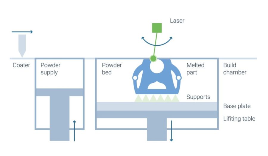
In L-PBF, productivity is primarily driven by the volume of material a laser melts per time interval. For certain materials, such as titanium alloys, physical limitations in melting speed already constrain productivity at today’s laser power levels. To overcome these constraints, recent advancements have focused on increasing the number of laser beam sources in machines. Modern multi-laser systems, equipped with 4, 8, or even more lasers, have drastically increased productivity, enabling build rates of over 100 cm³/h for certain materials. Simultaneously, advancements in machine architecture allow significantly larger build volumes, making these machines suitable for producing large parts or batch production of smaller components.
For layer heights around 50 µm, a single laser melts titanium or stainless steel powder at rates of 10–20 cm³/h and aluminum alloys at rates of 20–30 cm³/h. Increasing layer height can further improve these figures but often compromises resolution and surface quality. However, multi-laser systems effectively address these trade-offs by distributing the workload across multiple lasers, reducing build times without compromising accuracy or surface quality as significantly.
Non-productive times, such as recoating layers or taking quality assurance images, remain a limiting factor and can still constitute over 25% of the total process time. However, newer machines increasingly feature optimized recoating mechanisms and real-time monitoring systems that minimize these delays, further enhancing overall productivity.
The productivity of Binder Jetting (BJ) is driven by the coating and printing head’s speed across the powder layer. Announced BJ machines from DESKTOP METAL and HP incorporate single-pass coating and printing, processing the full width of the build envelope in one motion. This innovation makes productivity dependent on the packing density of parts in the build chamber—higher densities result in greater productivity while maintaining constant accuracy. Claimed green body printing rates reach several thousand cm³/h, but independent confirmation of such speeds remains limited. Depowdering and sintering times also significantly impact overall productivity.
In Material Extrusion (ME), the application rate is constrained by nozzle diameter and, for filament systems, by the speed at which the metal filament can be handled. Fragile filaments risk breaking at higher speeds, halting the process. Current build-up rates are around 15 cm³/h, but pellet-based systems offer potential for improved performance.
For Directed Energy Deposition (DED), productivity varies with system design, part geometry, and processing parameters. Cooling phases, influenced by part geometry, can consume up to 50% or more of total build time, negatively affecting productivity.
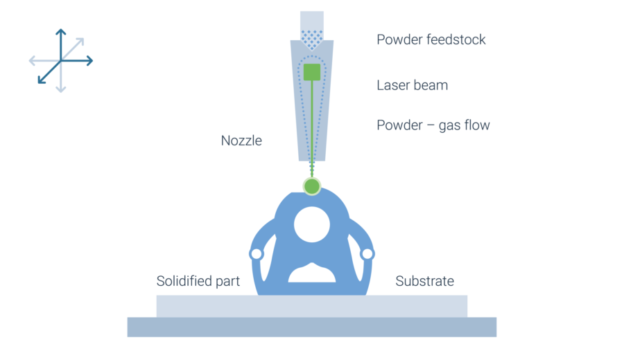
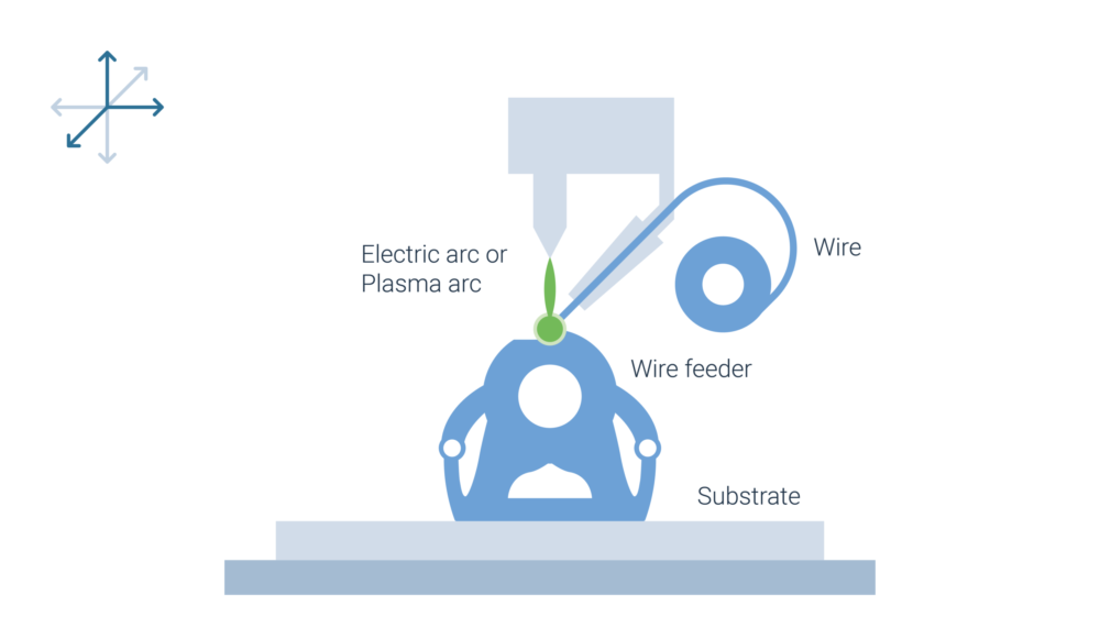
In Powder Laser Energy Deposition, nozzle diameter influences resolution and productivity, with rates ranging from 50 to 500 cm³/h. Wire Electric or Plasma Arc processes achieve build-up rates of 100 to 800 cm³/h, though with reduced accuracy compared to powder-based methods. For Wire Electric Arc Energy Deposition and Coldspray, rates can exceed 1,000 cm³/h, making them suitable for applications requiring high material deposition rather than fine precision.
Technology comparison
How do the different metal technologies compare?
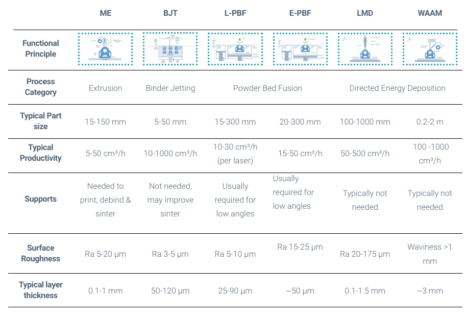
We therefore created an overview of the main metal technologies below that will help you choose the right technology for your needs. You can dive deeper into the different metal technologies at the bottom of this page.
Keep in mind that the values given below should only provide you a general rule of thumb – within each technology the exact values will differ depending on machine and material.
ME
BJT
L-PBF
E-PBF
LMD
WAAM
Functional Principle
Process Category
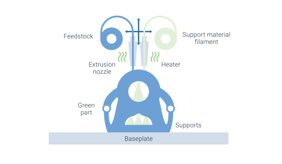
Extrusion
Binder Jetting
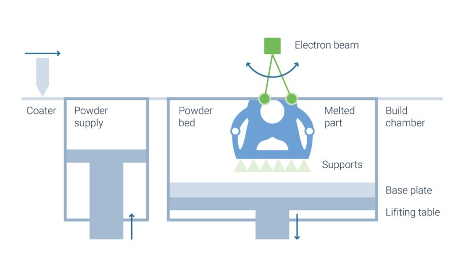
Powder Bed Fusion
Directed Energy Deposition
Typical Part size
15-250 mm
5-100 mm
15-300 mm
20-300 mm
100-1000 mm
0.2-2 m
Typical Productivity
5-50 cm³/h
10-1000 cm³/h
10-30 cm³/h (per laser)
15-50 cm³/h
50-500 cm³/h
100 -1000 cm³/h
Supports
Needed to print, debind & sinter
Not needed, may improve sinter
Usually required for low angles
Usually required for low angles
Typically not needed
Typically not needed
Surface Roughness
Ra 5-20 µm
Ra 3-5 µm
Ra 5-10 µm
Ra 15-25 µm
Ra 20-175 µm
Waviness >1 mm
Typical layer thickness
0.05-0.5 mm
50-120 µm
25-90 µm
~50 µm
0.1-1.5 mm
~3 mm
Metal AM Process Overview
How to get started
Usually more than one process for your application
The above table should provide you a general guideline how to get started selecting the right process. Keep in mind that often there is more than one process for your application. There are different databases, such as the SENVOL Database of Industrial AM machines and materials or the ANIWAA AM marketplace. These databases will allow you to narrow down the list of possible machines or materials by applying filters such as your material category, part dimensions or required part properties.
Once you have one or several technologies in mind, the next step is to reach out to an AM expert to discuss this in more detail.
Many different printing technologies - one sintering process
The sinter-based AM (SBAM) technologies have, as the name suggests, the sintering process in common. In this process, the printed green part is consolidated into a dense part and receives its final properties. The green part can be printed in advance using different technologies.They all have in common that metal powder is bound to the desired shape by a binder. The best-known printing technologies include Binder Jetting and Filament Material Extrusion.
In this section, you learn everything about the sinter-based AM process chain and get an overview of the different printing technologies.
Goal and structure of this course
This course is aimed at engineers,designers and other professionals that are working closely with sinter-based AM technologies. The goal is to cover the most important aspects that will enable engineers and designers to fully grasp the capabilities and technical limitations of the printing technologies and the sintering process to succeed in technology selection and part design. Besides going through the course from the beginning until the end, this course can also act as a constant source of knowledge while working on AM projects.
The course is structured into the following sections.
This section will start with an overview of the sinter-based AM process chain and its printing technologies, followed by a technology deep dive into the most important aspects of the BJT technology, followed by a closer look at the debinding and sintering step also including sintering simulation .
The second section will provide an overview of the different materials that are available as well as part characteristics that can be achieved with the BJT process and typical methods for quality assurance. Finally, several common defects in the BJT process are presented.
The last section will act as a guideline for designers. Besides generally describing the process when designing for Additive Manufacturing, actionable restrictions and guidelines for the BJT process are provided. The final section will present several design examples from different industries.
Simulation to compensate the deformation during the sintering step, nesting of parts and definition of printing parameters
Printing
Through various printing processes, different feedstocks such as metal powders, filaments, pellets or dispersions are processed into green parts
Unpacking
Unpacking of fragile green parts needs to be done carefully and is typically a manual process.
Debinding
Debinding describes the process of removing the binder which results in a brown part
Sintering
To reach the structural integrity of a metal part, a sinter process is required. The powder particles fuse together to a coherent, solid structure via a mass transport that occurs at the atomic scale driven via diffusional forces.
The brown part shrinks ~13-21 % in each direction.
The process chain of sinter-based technologies differs from other AM Technologies. Especially the post-printing processes (debinding and sintering) are crucial to achieve the intended mechanical properties.
Technology principle
How does Binder Jetting work?
Binder Jetting is a powder based Additive Manufacturing technology in which a liquid polymer binder is selectively deposited onto the powder bed binding the metal particles and forming a green body.
The metal powder is applied to a build platform in a typical layer thickness of 40 µm to 100 µm. Subsequently a modified 2D print head apply a binder selectively onto the powder bed. Depending on machine technology a hardening or curing process of the binder is performed in parallel for each layer and/or at the end of the whole build. During the in-situ curing process a heat source is used to solidify the binder and form a solid polymer – metal powder composite.
Working Principle of Binder Jetting
Afterwards the build platform moves downward by the amount of one layer thickness and a new layer of powder is applied. Again, the liquid binder is deposited and hardened in the required regions of the next layer to form the green body. This process is repeated until the complete part is printed. After the complete printing process is finished the parts have to be removed from the “powder cake” meaning the surrounding loose but densified powder. To improve the removal of the excess powder from the green body often brushes or a blasting gun with air pressure are used.
To create a dense metal part the 3D printed green body has to be post-processed in a debinding and sintering process. Similar to the metal injection molding process BJT parts are placed in a high temperature furnace, where the binder is burnt out and the remaining metal particles are sintered together. The sintering results in densification of the 3D printed green body to a metal part with high densities of 97 % to 99,5%, dependent of the material.
Technology Variation 1
Technology Variation 2
Technology Variation 3
Technology Variation 1
Binder Jetting with single print head
In classic Binder Jetting systems such as the ones distributed by EXONE or DIGITAL METAL the liquid binding agent is selectively deposited with a single print head. Meaning the width of the print head does not cover the full width of the powder bed. Therefore, the print head moves multiple times in xy-direction over the powder bed to completely cover the printing area and distributing the polymer binder.
Technology Variation 2
Binder Jetting with single pass jetting
The SINGLE PASS JETTING technology was developed by DESKTOP METAL and HEWLETT PACKARD. The width of the printing head covers the full width of the powder bed. When the printhead passes over the powder bed, binder is released from more than 30,000 small nozzles and the whole powder layer is selectively immersed in binder in one pass. The process is bi-directional which means that the binder deposition takes place in both moving directions of the printhead. With these modifications the printing speed is significantly increased.
A similarly fast technology is the METAL JET process by HEWLETT PACKARD. In a single pass, a liquid printing agent is applied to the powder layer and subsequently partially evaporated to form the binding polymer around the metal powder. After the completion of the print an additional curing to achieve the full green body stability is needed.
Technology Variation 3
Binder Jetting with full layer jetting
3DEO combines the Binder Jetting process with a subsequent machining process. Different from conventional Binder Jetting processes, the binder is not only deposited selectively but onto the entire powder layer. After hardening of the complete layer, the part geometry is shaped through a milling process every couple of layers by cutting the part contour out of the binder powder composite.
Printing Technologies
Metal Binder Jetting
Binder Jetting is a powder based Additive Manufacturing technology in which a liquid polymer binder is selectively deposited onto the powder bed binding the metal particles and forming a green body.
The metal powder is applied to a build platform in a typical layer thickness of 40 µm to 100 µm. Subsequently a modified 2D print head apply a binder selectively onto the powder bed. Depending on machine technology a hardening or curing process of the binder is performed in parallel for each layer and/or at the end of the whole build. During the in-situ curing process a heat source is used to solidify the binder and form a solid polymer – metal powder composite.
Working Principle of Binder Jetting
Material Extrusion
Binder Jetting is a powder based Additive Manufacturing technology in which a liquid polymer binder is selectively deposited onto the powder bed binding the metal particles and forming a green body.
The metal powder is applied to a build platform in a typical layer thickness of 40 µm to 100 µm. Subsequently a modified 2D print head apply a binder selectively onto the powder bed. Depending on machine technology a hardening or curing process of the binder is performed in parallel for each layer and/or at the end of the whole build. During the in-situ curing process a heat source is used to solidify the binder and form a solid polymer – metal powder composite.
Working Principle of Binder Jetting
Mold Slurry Deposition
Binder Jetting is a powder based Additive Manufacturing technology in which a liquid polymer binder is selectively deposited onto the powder bed binding the metal particles and forming a green body.
The metal powder is applied to a build platform in a typical layer thickness of 40 µm to 100 µm. Subsequently a modified 2D print head apply a binder selectively onto the powder bed. Depending on machine technology a hardening or curing process of the binder is performed in parallel for each layer and/or at the end of the whole build. During the in-situ curing process a heat source is used to solidify the binder and form a solid polymer – metal powder composite.
Working Principle of Binder Jetting
Metal Selective Laser Sintering
Binder Jetting is a powder based Additive Manufacturing technology in which a liquid polymer binder is selectively deposited onto the powder bed binding the metal particles and forming a green body.
The metal powder is applied to a build platform in a typical layer thickness of 40 µm to 100 µm. Subsequently a modified 2D print head apply a binder selectively onto the powder bed. Depending on machine technology a hardening or curing process of the binder is performed in parallel for each layer and/or at the end of the whole build. During the in-situ curing process a heat source is used to solidify the binder and form a solid polymer – metal powder composite.