Polymer Technology Selection
Which Polymer 3D Printing Technology Is Best for Your Application?
Share article
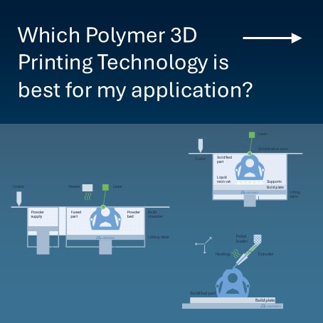


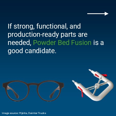

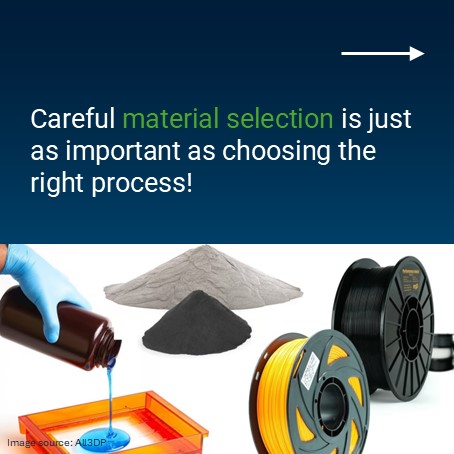


Choosing the right polymer 3D printing technology is essential for achieving optimal performance, cost efficiency, and part quality. With several methods available, each offering unique advantages and trade-offs, it’s crucial to understand which process best fits your application.
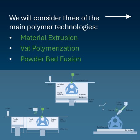
In this guide, we compare the three most widely used industrial polymer 3D printing methods:
This guide serves as a starting point, but no single 3D printing technology is always the best choice. In many applications, multiple processes can achieve the desired results, each with trade-offs in cost, accuracy, strength, and post-processing. Additionally, there is a wide variation within each technology—for example, SLA quality differs significantly between low-cost desktop printers and industrial machines. Material selection also plays a crucial role, as for example fiber-reinforced extrusion parts significantly outperform basic materials in strength. To make an informed decision, always consider both the printing technology and the material properties together.
Material Extrusion, Vat Polymerization, and Powder Bed Fusion are among the most mature and widely used polymer 3D printing technologies. Each process offers distinct advantages, making them suitable for different applications – from low-cost prototyping to high-precision components and strong, production-ready parts.
In this section, we will provide an overview of each technology, explore their key variations, and highlight their strengths and limitations to help you understand which process best fits your application needs.
Key Advantages:
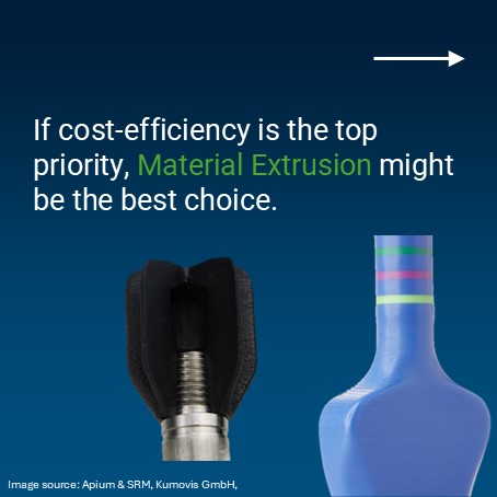
✔️ Low-cost and accessible (widely used for prototyping)
✔️ Broad material selection for functional applications
✔️ High-strenght possible (e.g. PEEK and Fiber-reinforcement)
Limitations:
❌ Lower resolution & visible layer lines
❌ Weaker interlayer bonding (anisotropic strength)
❌ Requires support structures for overhangs
💡 Best suited for:
Basic prototypes, jigs & fixtures, tooling, and proof-of-concept models
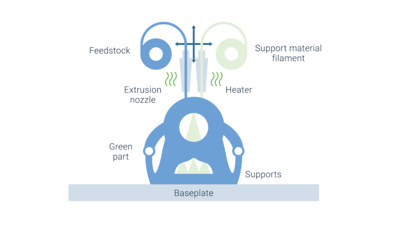
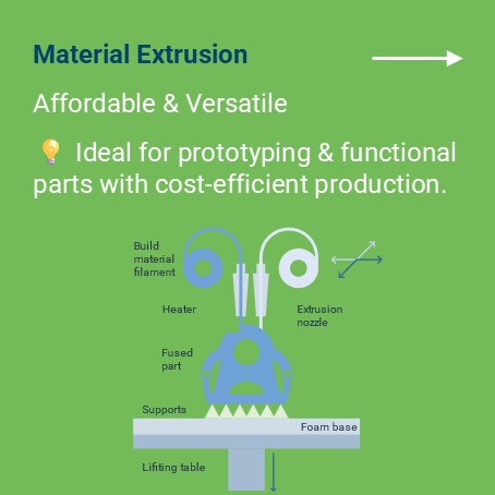
Process: A thermoplastic filament (PLA, ABS, PETG, TPU, Nylon) is melted and extruded through a nozzle, layering the material to form a part.
Process: Pellet-based Material Extrusion is a high-throughput variation of traditional filament-based extrusion, using pelletized feedstock instead of filament
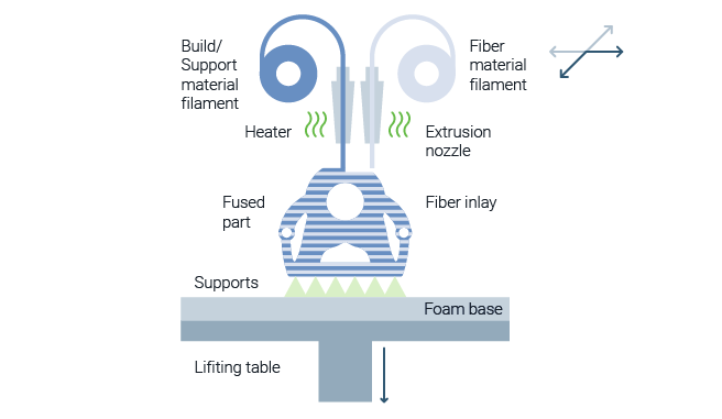
Process: Continuous Fiber ME is a variation of filament extrusion, where a continuous fiber—such as carbon or glass – is embedded within a thermoplastic matrix during printing.
Key Advantages:
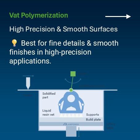
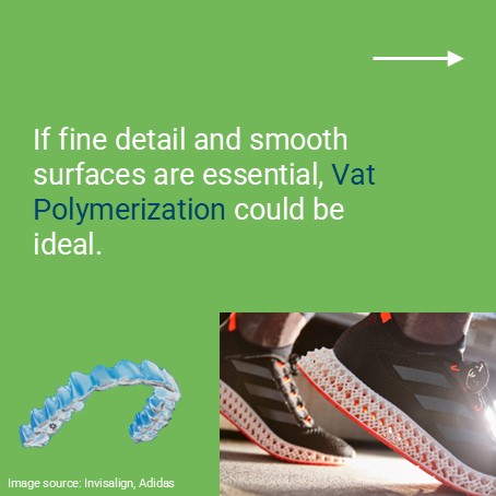
✔️ High-detail resolution for intricate features
✔️ Smooth, injection-mold-like surface finish
✔️ Good for small, precise, aesthetic components
Limitations:
❌ Requires post-processing (washing, curing, support removal)
❌ Brittle materials (resins are less impact-resistant than thermoplastics)
❌ Limited functional applications due to material properties
💡 Best suited for:
Dental models, medical devices, jewelry, high-detail prototypes, and master molds for casting
Process: A UV laser selectively cures liquid resin, solidifying the object layer by layer.
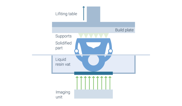
Process: A digital light projector selectively cures liquid resin, solidifying the object layer by layer.
Key Advantages:
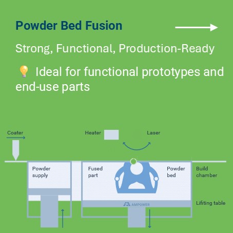
✔️ No support structures needed (powder bed acts as support)
✔️ Strong, isotropic mechanical properties (ideal for functional parts)
✔️ Good for batch production of durable components
Limitations:
❌ Higher cost & complex powder handling
❌ Rougher surface finish compared to SLA
❌ Post-processing required (powder removal, finishing)
💡 Best suited for:
Functional prototypes, aerospace and automotive parts, production components, and end-use goods
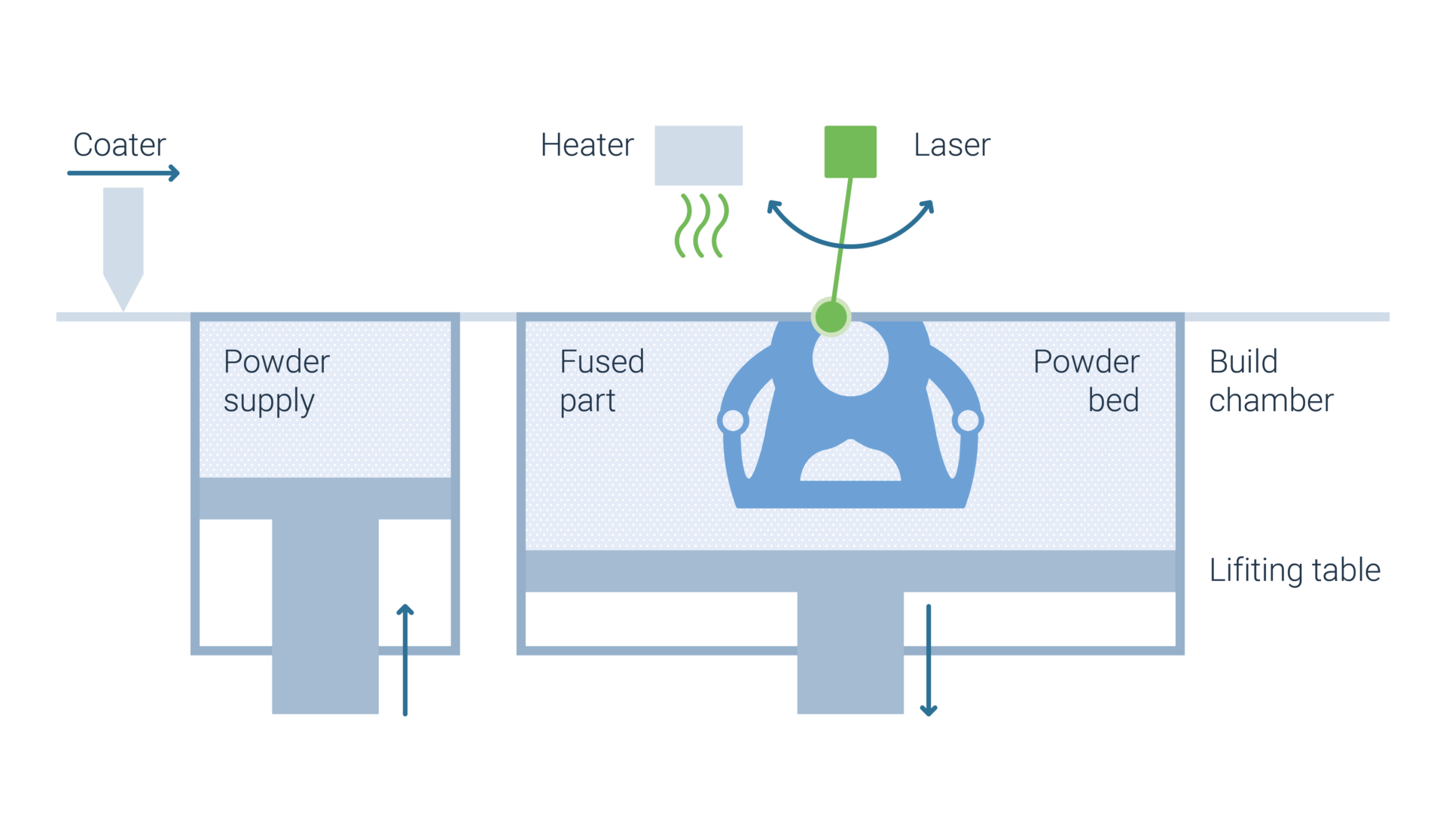
Process: A thermoplastic filament (PLA, ABS, PETG, TPU, Nylon) is melted and extruded through a nozzle, layering the material to form a part.
Process: A thermoplastic filament (PLA, ABS, PETG, TPU, Nylon) is melted and extruded through a nozzle, layering the material to form a part.
Selecting the right technology requires balancing accuracy, strength, material compatibility, and cost. Each process offers unique advantages and trade-offs that impact the final part’s performance, surface quality, and production efficiency.
The table below provides a quick comparison of these technologies, highlighting key factors such as resolution, durability, material options, post-processing needs, and cost-efficiency to help guide your decision-making.
| wdt_ID | Factor | Material Extrusion | Stereolithography | Powder Bed Fusion |
|---|---|---|---|---|
| 1 | Accuracy & Resolution | ★★★☆☆ | ★★★★★ | ★★★★☆ |
| 2 | Surface Finish | ★★☆☆☆
(Visible layer lines) |
★★★★★
(Smooth, detailed) |
★★★☆☆
(Slightly rough) |
| 3 | Strength & Durability | ★★★★☆ (Fiber-reinforced parts with higher strength |
★★☆☆☆
(Brittle) |
★★★★★ (Strong, isotropic) |
| 4 | Material Options | PLA, ABS, PETG, Nylon, TPU | Rigid, Tough, Flexible, Clear, Dental Resins | Nylon PA11, PA12, TPU, Polypropylene |
| 5 | Support structures | Yes | Yes | No |
| 6 | Post-Processing | Minimal | Cleaning, UV curing | Powder removal, finishing |
| 7 | Productivity | ★★☆☆☆ | ★★★☆☆ | ★★★★☆ |
| 8 | Cost-efficiency | ★★★★★
(Low cost) |
★★★☆☆
(Mid-range) |
★★☆☆☆
(Higher cost) |
Post-processing is an essential step in 3D printing that impacts cost, workflow efficiency, and final part quality. The level of post-processing required varies significantly between Material Extrusion, Vat Polymerization, and Powder Bed Fusion, affecting both time and effort in the production process.
Understanding these post-processing needs is critical when selecting a technology that aligns with your application’s efficiency and quality requirements.
✔️ Best for: Functional testing, jigs & fixtures, educational use
✔️ Material Options: PLA, ABS, PETG, TPU, Nylon
✔️ Limitations: Lower resolution, weaker interlayer bonding
✔️ Best for: Jewelry, dental, medical, casting masters, visual prototypes
✔️ Material Options: Standard, tough, flexible, clear, and dental resins
✔️ Limitations: Brittle materials, requires post-processing
✔️ Best for: Aerospace, automotive, industrial applications
✔️ Material Options: Nylon PA12, PA11, TPU, Polypropylene
✔️ Limitations: Higher cost, rougher surface finish
Selecting the right polymer 3D printing technology depends on your specific needs, budget, and required material properties. Some key takeaways:
Would you like to further increase your 3D Printing knowledge?
You can try out the AM Fundamentals course of the AMPOWER Academy free of charge
Understand the most important topics to get started with Additive Manufacturing
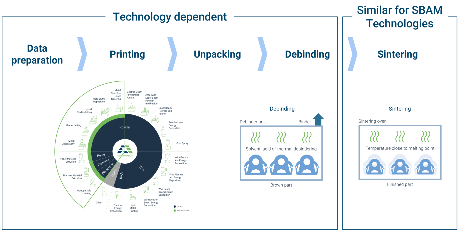
The sinter-based AM (SBAM) technologies have, as the name suggests, the sintering process in common. In this process, the printed green part is consolidated into a dense part and receives its final properties. The green part can be printed in advance using different technologies.They all have in common that metal powder is bound to the desired shape by a binder. The best-known printing technologies include Binder Jetting and Filament Material Extrusion.
In this section, you learn everything about the sinter-based AM process chain and get an overview of the different printing technologies.
This course is aimed at engineers, designers and other professionals that are working closely with sinter-based AM technologies. The goal is to cover the most important aspects that will enable engineers and designers to fully grasp the capabilities and technical limitations of the printing technologies and the sintering process to succeed in technology selection and part design. Besides going through the course from the beginning until the end, this course can also act as a constant source of knowledge while working on AM projects.
The course is structured into the following sections.
This section will start with an overview of the sinter-based AM process chain and its printing technologies, followed by a technology deep dive into the most important aspects of the BJT technology, followed by a closer look at the debinding and sintering step also including sintering simulation .
The second section will provide an overview of the different materials that are available as well as part characteristics that can be achieved with the BJT process and typical methods for quality assurance. Finally, several common defects in the BJT process are presented.
The last section will act as a guideline for designers. Besides generally describing the process when designing for Additive Manufacturing, actionable restrictions and guidelines for the BJT process are provided. The final section will present several design examples from different industries.
Simulation to compensate the deformation during the sintering step, nesting of parts and definition of printing parameters
Through various printing processes, different feedstocks such as metal powders, filaments, pellets or dispersions are processed into green parts
Unpacking of fragile green parts needs to be done carefully and is typically a manual process.
Debinding describes the process of removing the binder which results in a brown part
To reach the structural integrity of a metal part, a sinter process is required. The powder particles fuse together to a coherent, solid structure via a mass transport that occurs at the atomic scale driven via diffusional forces.
The brown part shrinks ~13-21 % in each direction.
The process chain of sinter-based technologies differs from other AM Technologies. Especially the post-printing processes (debinding and sintering) are crucial to achieve the intended mechanical properties.
Binder Jetting is a powder based Additive Manufacturing technology in which a liquid polymer binder is selectively deposited onto the powder bed binding the metal particles and forming a green body.
The metal powder is applied to a build platform in a typical layer thickness of 40 µm to 100 µm. Subsequently a modified 2D print head apply a binder selectively onto the powder bed. Depending on machine technology a hardening or curing process of the binder is performed in parallel for each layer and/or at the end of the whole build. During the in-situ curing process a heat source is used to solidify the binder and form a solid polymer – metal powder composite.
Afterwards the build platform moves downward by the amount of one layer thickness and a new layer of powder is applied. Again, the liquid binder is deposited and hardened in the required regions of the next layer to form the green body. This process is repeated until the complete part is printed. After the complete printing process is finished the parts have to be removed from the “powder cake” meaning the surrounding loose but densified powder. To improve the removal of the excess powder from the green body often brushes or a blasting gun with air pressure are used.
To create a dense metal part the 3D printed green body has to be post-processed in a debinding and sintering process. Similar to the metal injection molding process BJT parts are placed in a high temperature furnace, where the binder is burnt out and the remaining metal particles are sintered together. The sintering results in densification of the 3D printed green body to a metal part with high densities of 97 % to 99,5%, dependent of the material.
In classic Binder Jetting systems such as the ones distributed by EXONE or DIGITAL METAL the liquid binding agent is selectively deposited with a single print head. Meaning the width of the print head does not cover the full width of the powder bed. Therefore, the print head moves multiple times in xy-direction over the powder bed to completely cover the printing area and distributing the polymer binder.
The SINGLE PASS JETTING technology was developed by DESKTOP METAL and HEWLETT PACKARD. The width of the printing head covers the full width of the powder bed. When the printhead passes over the powder bed, binder is released from more than 30,000 small nozzles and the whole powder layer is selectively immersed in binder in one pass. The process is bi-directional which means that the binder deposition takes place in both moving directions of the printhead. With these modifications the printing speed is significantly increased.
A similarly fast technology is the METAL JET process by HEWLETT PACKARD. In a single pass, a liquid printing agent is applied to the powder layer and subsequently partially evaporated to form the binding polymer around the metal powder. After the completion of the print an additional curing to achieve the full green body stability is needed.
3DEO combines the Binder Jetting process with a subsequent machining process. Different from conventional Binder Jetting processes, the binder is not only deposited selectively but onto the entire powder layer. After hardening of the complete layer, the part geometry is shaped through a milling process every couple of layers by cutting the part contour out of the binder powder composite.
Binder Jetting is a powder based Additive Manufacturing technology in which a liquid polymer binder is selectively deposited onto the powder bed binding the metal particles and forming a green body.
The metal powder is applied to a build platform in a typical layer thickness of 40 µm to 100 µm. Subsequently a modified 2D print head apply a binder selectively onto the powder bed. Depending on machine technology a hardening or curing process of the binder is performed in parallel for each layer and/or at the end of the whole build. During the in-situ curing process a heat source is used to solidify the binder and form a solid polymer – metal powder composite.