Success Story
The power of 3D Printing and automated design for jigs & fixtures
AMPOWER Academy 3D Printing and automated design for jigs & fixtures Trinckle, Audi Sport, Deutsche Bahn Tooling, jigs & fixtures
Collaborative Efforts, Expertise, and Know-How Lead to Thriving 3D Printing Applications in TRUMPF Machines
In addition to its core operations, TRUMPF has recently entered the 3D Printing market with its Laser Powder Bed Fusion machine for metal. This article, however, focuses on the company’s internal 3D Printing applications, which have been successfully integrated into various TRUMPF machines. As a technology leader, TRUMPF offers highly productive and complex machines, which provide an ideal foundation for exploring new 3D Printing use cases.
Applications for 3D Printing had been identified at TRUMPF on a case-by-case basis. Trained engineers proposed potential applications and a team of 3D Printing experts evaluated the potential and worked with the part owners on developing a successful use case. At the same time, the top-down support from CTO level was a critical success factor, since it fueled acceptance for 3D Printing among the management levels and increased enthusiasm among stakeholders.
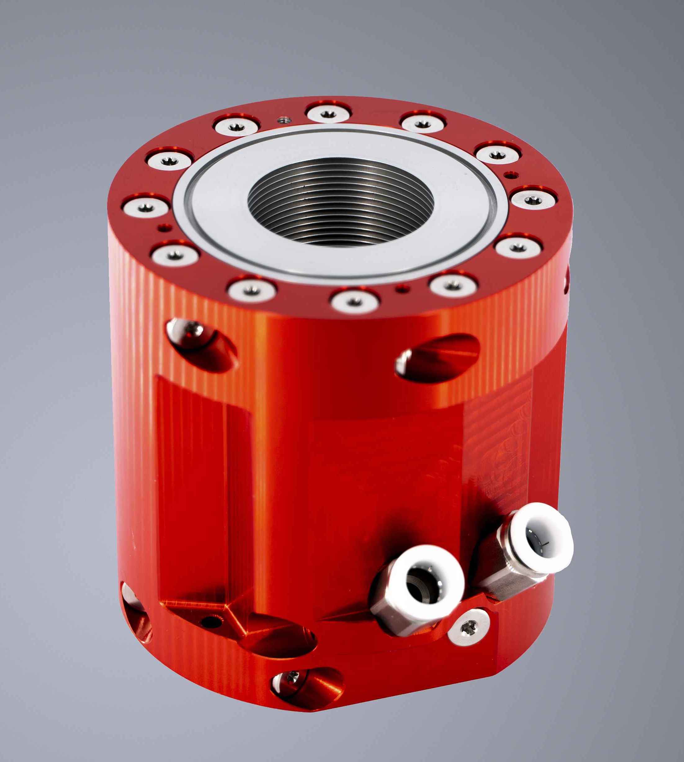
When it comes to specific applications, fluid guiding components have proven to be a highly successful area for 3D Printing applications at TRUMPF, for several reasons. Firstly, these components often have a high risk of leakage at every joint, which can be reduced by successful 3D Printing designs that minimize the number of components. Secondly, fluid guiding components tend to be highly complex, with internal structures that are difficult to manufacture conventionally. Moreover, the channels are often intricately wound around areas that require cooling or heating, making conventional designs both expensive to produce and difficult to test and assure for quality due to the increased risk of leakage.
Lesson 1
All applications that guide fluids have a high potential for success.
3D Printing has also proven to be a successful solution for solid joints, which can be difficult and expensive to manufacture using conventional designs that require extensive manual calibration. TRUMPF has demonstrated the effectiveness of using AM to produce these parts. Most of the early use cases involved small parts that could be easily nested on a platform of a TRUMPF 3D Printing machine. Large parts that utilize the full build platform are more challenging to produce and require careful design considerations to minimize the cost of production.
While the slogan “complexity is for free” is often associated with 3D Printing, it is important to note that this technology can be expensive if the design is not well thought through. By educating engineers on how to design for 3D Printing, TRUMPF has been able to unlock the full potential of this innovative technology. However, it’s not just engineers who can benefit from a basic understanding of 3D Printing. Procurement teams, for example, can also identify potential applications where 3D Printing can help solve supply chain or quality issues.
Similarly, technicians and quality engineers on the shop floor or in process development departments can identify areas where 3D Printing can improve production processes or solve quality issues. For example, they may identify parts that are difficult or expensive to produce using traditional manufacturing methods or have continuing quality issues.
Overall, by empowering key personnel with an understanding of 3D Printing, TRUMPF has been able to unlock its full potential and create new opportunities for innovation and cost savings. This has helped the company stay ahead of the curve in a highly competitive industry and continue to deliver value to its customers.
Lesson 2
Complexity is free but not free of charge.
3D Printing Knowhow is Key.
Implementing 3D Printing in a company that has been around for 100 years can be a time-consuming process. Established designs and processes that have been proven over centuries are now being challenged by a completely new metal manufacturing technology, causing both excitement and apprehension. Engineers who are responsible for the safe and reliable functionality of a component may be hesitant to trust a new manufacturing technology.
Despite numerous guidelines and handbooks on correct design and proven material properties for 3D Printing, experience and established standards are still lacking. This challenge can be overcome by close collaboration between 3D Printing experts, responsible part owners, and management. All three stakeholders must be fully committed to developing successful 3D Printing applications, while also addressing legitimate concerns and building trust through real data.
In summary, successfully implementing 3D Printing in a company with a long history requires a collaborative effort that takes into account legitimate concerns and leverages the expertise of all stakeholders involved. By doing so, the company can successfully integrate 3D Printing into its manufacturing processes, leading to greater innovation and competitiveness in the marketplace.
Learning 3
3D Printing applications are successful when 3D Printing Experts, part owners and management are working together.
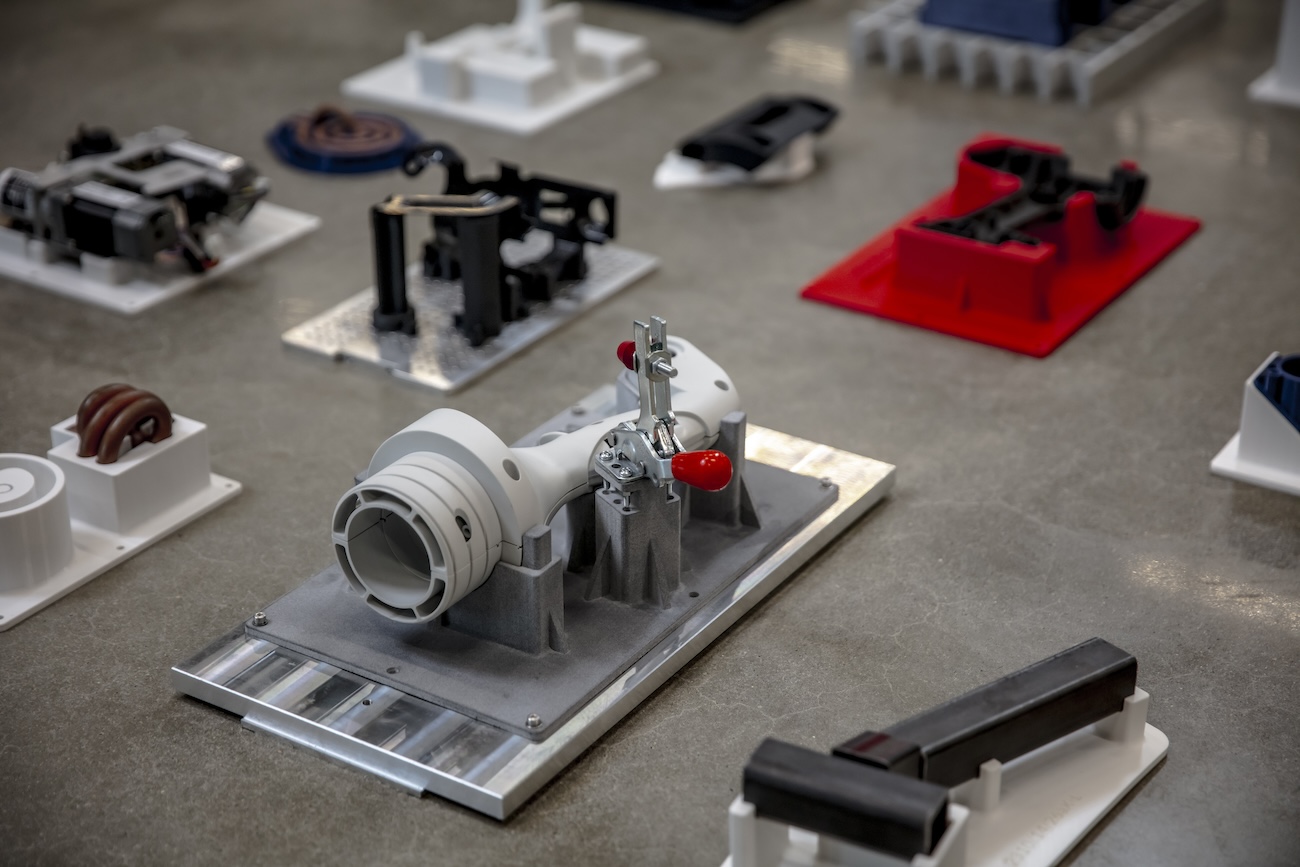
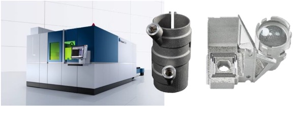
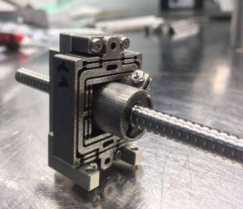
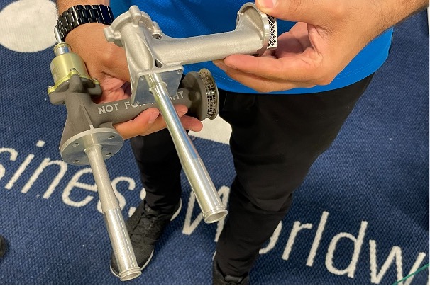
The following images show how applications have been re-designed for Additive Manufacturing. In case of any questions or inquiries, you can reach out to [email protected] Additional information can be found on the TRUMPF website.
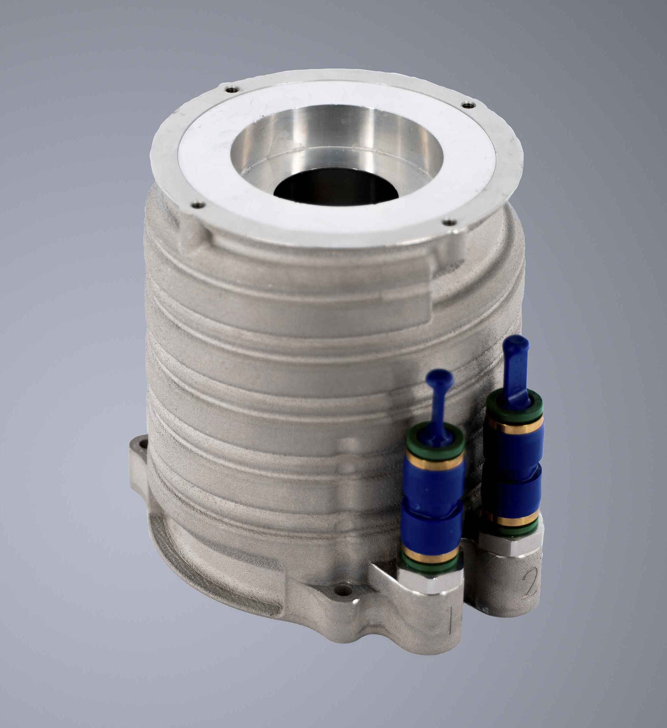

Conventional design:
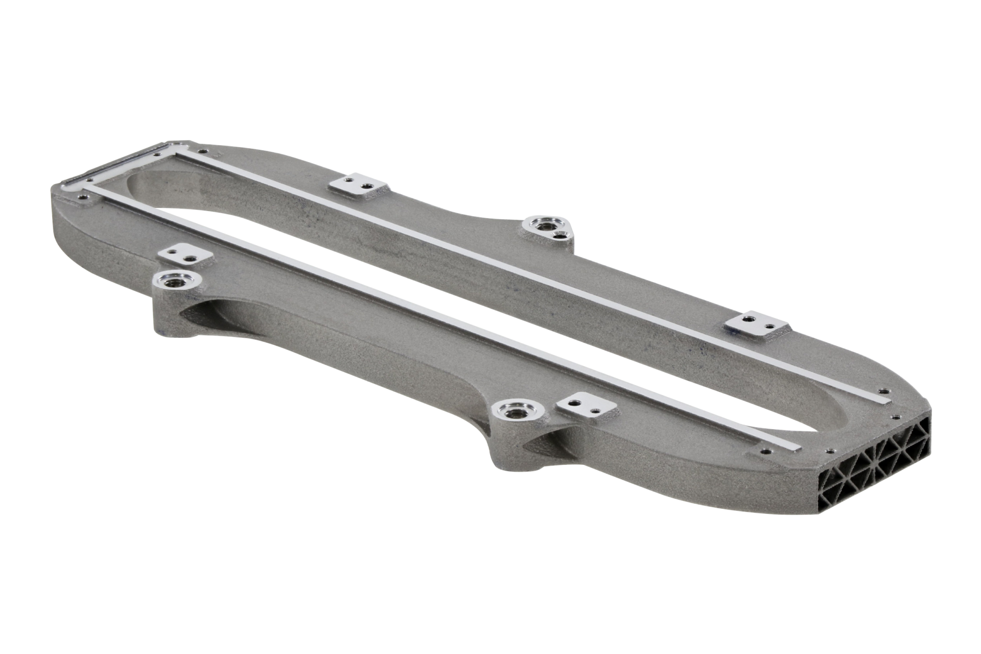
AM design:
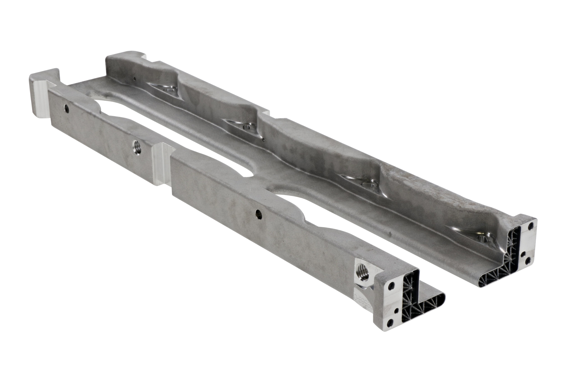
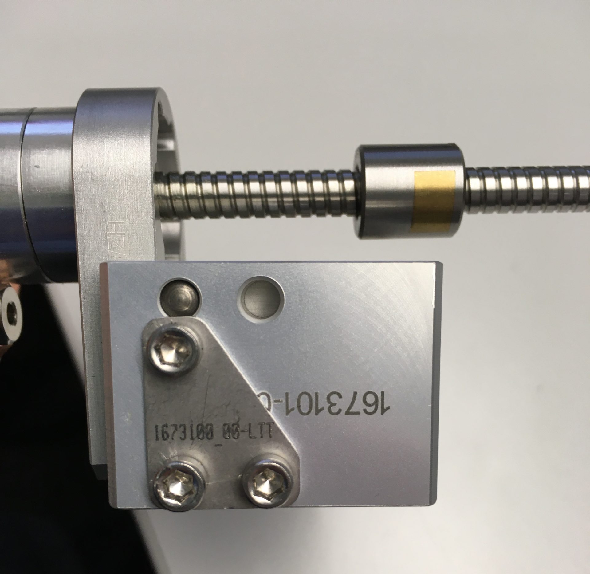
Conventional design:
AM design:
Besides being one of the leading supplier of machines for metal 3D Printing, TRUMPF successfully implemented the technology in several different areas. In this process, 3 key learnings where identified that can help industrial companies to successfully implement 3D Printing:
AMPOWER Academy 3D Printing and automated design for jigs & fixtures Trinckle, Audi Sport, Deutsche Bahn Tooling, jigs & fixtures
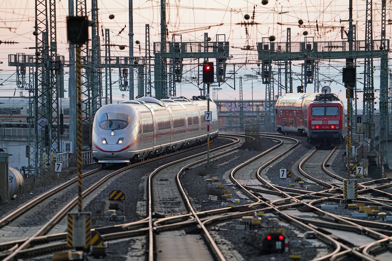
AMPOWER Academy 3D printing at Deutsche Bahn Deutsche Bahn Railway Berlin, Germany 26.09.2023 Share article Frankfurt (Main) Hbf – Einfahrt
AMPOWER Academy 3D printing at Eaton Aerospace Fueling progress: How Eaton Aerospace’s dedication to 3D Printing elevated aircraft performance Eaton
Would you like to further advance your 3D Printing success story? We learned that training a broad number of employees is key to increase the usage of 3D Printing in a company and to successfully launch new applications.
You can try out the AM Fundamentals course of the AMPOWER Academy free of charge
Understand the most important topics to get started with Additive Manufacturing
The sinter-based AM (SBAM) technologies have, as the name suggests, the sintering process in common. In this process, the printed green part is consolidated into a dense part and receives its final properties. The green part can be printed in advance using different technologies.They all have in common that metal powder is bound to the desired shape by a binder. The best-known printing technologies include Binder Jetting and Filament Material Extrusion.
In this section, you learn everything about the sinter-based AM process chain and get an overview of the different printing technologies.

This course is aimed at engineers, designers and other professionals that are working closely with sinter-based AM technologies. The goal is to cover the most important aspects that will enable engineers and designers to fully grasp the capabilities and technical limitations of the printing technologies and the sintering process to succeed in technology selection and part design. Besides going through the course from the beginning until the end, this course can also act as a constant source of knowledge while working on AM projects.
The course is structured into the following sections.
This section will start with an overview of the sinter-based AM process chain and its printing technologies, followed by a technology deep dive into the most important aspects of the BJT technology, followed by a closer look at the debinding and sintering step also including sintering simulation .
The second section will provide an overview of the different materials that are available as well as part characteristics that can be achieved with the BJT process and typical methods for quality assurance. Finally, several common defects in the BJT process are presented.
The last section will act as a guideline for designers. Besides generally describing the process when designing for Additive Manufacturing, actionable restrictions and guidelines for the BJT process are provided. The final section will present several design examples from different industries.
Simulation to compensate the deformation during the sintering step, nesting of parts and definition of printing parameters
Through various printing processes, different feedstocks such as metal powders, filaments, pellets or dispersions are processed into green parts
Unpacking of fragile green parts needs to be done carefully and is typically a manual process.
Debinding describes the process of removing the binder which results in a brown part
To reach the structural integrity of a metal part, a sinter process is required. The powder particles fuse together to a coherent, solid structure via a mass transport that occurs at the atomic scale driven via diffusional forces.
The brown part shrinks ~13-21 % in each direction.
The process chain of sinter-based technologies differs from other AM Technologies. Especially the post-printing processes (debinding and sintering) are crucial to achieve the intended mechanical properties.
Binder Jetting is a powder based Additive Manufacturing technology in which a liquid polymer binder is selectively deposited onto the powder bed binding the metal particles and forming a green body.
The metal powder is applied to a build platform in a typical layer thickness of 40 µm to 100 µm. Subsequently a modified 2D print head apply a binder selectively onto the powder bed. Depending on machine technology a hardening or curing process of the binder is performed in parallel for each layer and/or at the end of the whole build. During the in-situ curing process a heat source is used to solidify the binder and form a solid polymer – metal powder composite.

Afterwards the build platform moves downward by the amount of one layer thickness and a new layer of powder is applied. Again, the liquid binder is deposited and hardened in the required regions of the next layer to form the green body. This process is repeated until the complete part is printed. After the complete printing process is finished the parts have to be removed from the “powder cake” meaning the surrounding loose but densified powder. To improve the removal of the excess powder from the green body often brushes or a blasting gun with air pressure are used.
To create a dense metal part the 3D printed green body has to be post-processed in a debinding and sintering process. Similar to the metal injection molding process BJT parts are placed in a high temperature furnace, where the binder is burnt out and the remaining metal particles are sintered together. The sintering results in densification of the 3D printed green body to a metal part with high densities of 97 % to 99,5%, dependent of the material.
In classic Binder Jetting systems such as the ones distributed by EXONE or DIGITAL METAL the liquid binding agent is selectively deposited with a single print head. Meaning the width of the print head does not cover the full width of the powder bed. Therefore, the print head moves multiple times in xy-direction over the powder bed to completely cover the printing area and distributing the polymer binder.
The SINGLE PASS JETTING technology was developed by DESKTOP METAL and HEWLETT PACKARD. The width of the printing head covers the full width of the powder bed. When the printhead passes over the powder bed, binder is released from more than 30,000 small nozzles and the whole powder layer is selectively immersed in binder in one pass. The process is bi-directional which means that the binder deposition takes place in both moving directions of the printhead. With these modifications the printing speed is significantly increased.
A similarly fast technology is the METAL JET process by HEWLETT PACKARD. In a single pass, a liquid printing agent is applied to the powder layer and subsequently partially evaporated to form the binding polymer around the metal powder. After the completion of the print an additional curing to achieve the full green body stability is needed.
3DEO combines the Binder Jetting process with a subsequent machining process. Different from conventional Binder Jetting processes, the binder is not only deposited selectively but onto the entire powder layer. After hardening of the complete layer, the part geometry is shaped through a milling process every couple of layers by cutting the part contour out of the binder powder composite.
Binder Jetting is a powder based Additive Manufacturing technology in which a liquid polymer binder is selectively deposited onto the powder bed binding the metal particles and forming a green body.
The metal powder is applied to a build platform in a typical layer thickness of 40 µm to 100 µm. Subsequently a modified 2D print head apply a binder selectively onto the powder bed. Depending on machine technology a hardening or curing process of the binder is performed in parallel for each layer and/or at the end of the whole build. During the in-situ curing process a heat source is used to solidify the binder and form a solid polymer – metal powder composite.
