Success Story
3D printing at Deutsche Bahn
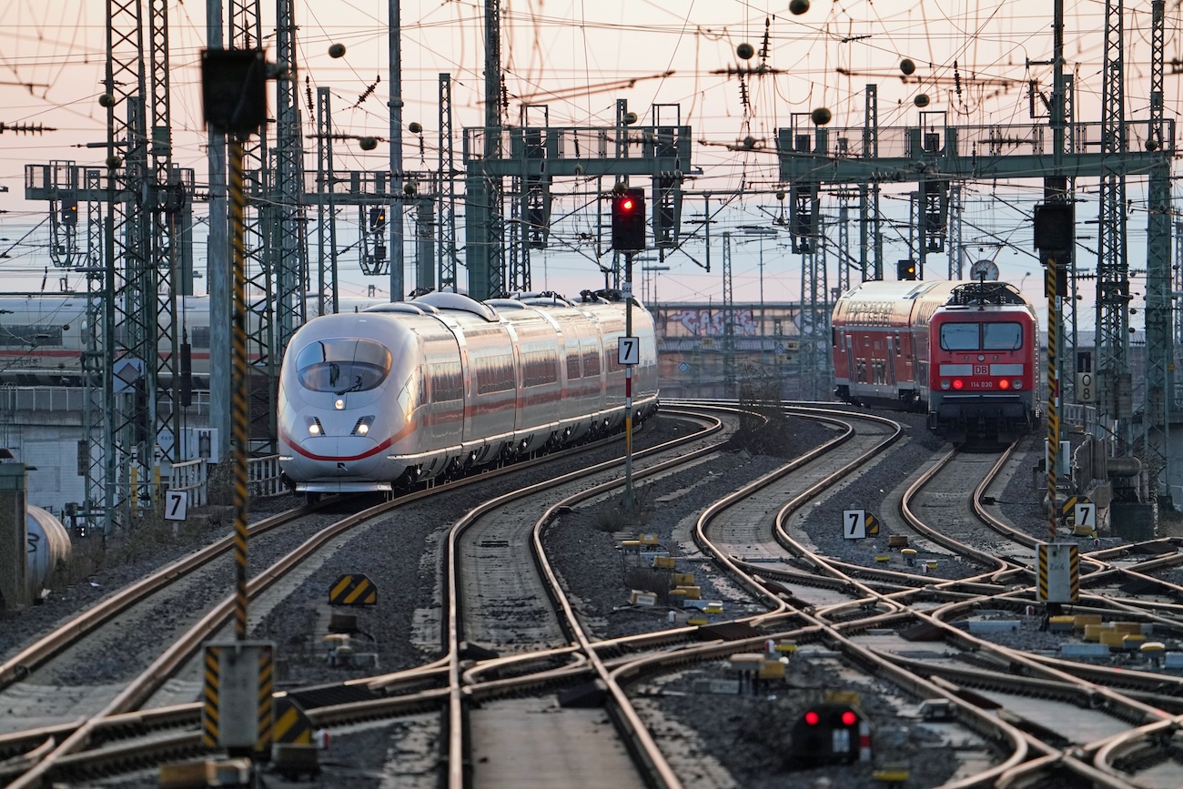
AMPOWER Academy 3D printing at Deutsche Bahn Deutsche Bahn Railway Berlin, Germany 26.09.2023 Share article Frankfurt (Main) Hbf – Einfahrt


AMPOWER Academy 3D printing at Deutsche Bahn Deutsche Bahn Railway Berlin, Germany 26.09.2023 Share article Frankfurt (Main) Hbf – Einfahrt
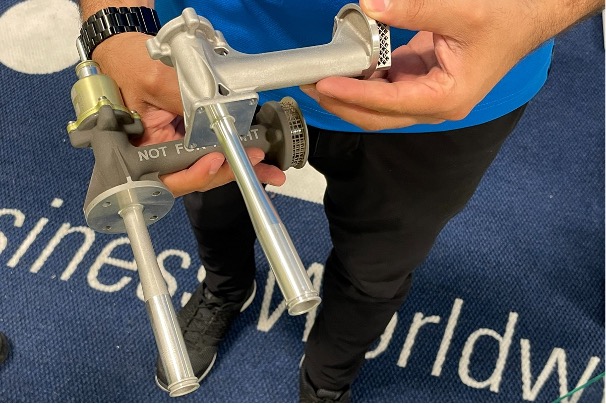
AMPOWER Academy 3D printing at Eaton Aerospace Fueling progress: How Eaton Aerospace’s dedication to 3D Printing elevated aircraft performance Eaton
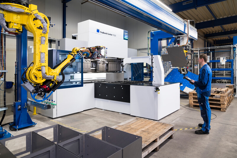
AMPOWER Academy 3D Printing in TRUMPF machines Collaborative Efforts, Expertise, and Know-How Lead to Thriving 3D Printing Applications in TRUMPF


